Kichler 42947 Manuel d'utilisation
Page 2
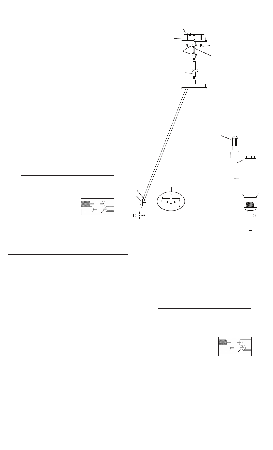
LOOP/CHAIN LINK MOUNT INSTALLATION
1) Align holes in plate on bottom of arm with holes on inside of ring.
2) Thread screws into holes in plate and into ring. Tighten screws to
secure arm to ring. Repeat for remaining arms.
3) Pass wire through stem and screw stem into coupling on top of
fixture body. NOTE: Thread locking compound must be applied to all
stem threads as noted with symbol (3) to prevent accidental rotation of
fixture during cleaning, relamping, etc.
4) Pass fixture wire through remaining stems and screw stems together.
5) OPTIONAL STEP: Pass decorative cap over end of stem.
6) Screw small loop on to top of stem.
7) Pass threaded pipe through hole in canopy.
8) Slip lockwasher over threaded pipe protruding from inside of canopy.
Screw hexnut onto threaded pipe.
9) Attach chain link to small loop at end of stem and to loop on canopy.
10) TURN OFF POWER.
IMPORTANT: Before you start, NEVER attempt any work without
shutting off the electricity until the work is done.
a) Go to the main fuse, or circuit breaker, box in your home. Place
the main power switch in the “OFF” position.
b) Unscrew the fuse(s), or switch “OFF” the circuit breaker switch(s),
that control the power to the fixture or room that you are working on.
c) Place the wall switch in the “OFF” position. If the fixture to be
replaced has a switch or pull chain, place those in the “OFF”
position.
11) Find the appropriate threaded holes on mounting strap. Assemble
mounting screws into threaded holes.
12) Attach mounting strap to outlet box. (Screws not provided) Mounting
strap can be adjusted to suit position of fixture.
13) Make wire connections (connectors not provided). Reference chart
below for correct connections and wire accordingly.
14) Push fixture to ceiling, carefully passing mounting screws through holes
in canopy.
15) Secure fixture to ceiling with threaded balls.
16) Set glass down over sockets.
17) Attach socket ring to socket ring tool.
18) Lower socket ring tool with socket ring attached down through glass.
Thread socket ring onto socket. Tighten socket ring to secure glass in
place. (DO NOT over tighten.)
INSTALLATION DES LIENS EN BOUCLE/MAILLON
1) Aligner les trous dans la plaque sur la partie inférieure du bras avec
ceux situés à l’intérieur de l’anneau.
2) Serrer les vis dans les trous de la plaque et dans l’anneau. Serrer les
vis pour fixer le bras à l’anneau. Répéter l’opération pour les autres
bras.
3) Acheminer le fil du luminaire par la tige et visser la tige en haut du luminaire.
REMARQUE : appliquer le frein filet sur tous les filets de la tige
indiqués par le symbole (3) pour empêcher la rotation accidentelle
du luminaire pendant le nettoyage, remplacement de lampe, etc.
4) Acheminer le fil du luminaire par les tiges restantes et visser les tiges
ensemble.
5) ÉTAPE OPTIONNELLE : Placer un bouchon décoratif sur chaque tige.
6) Visser la petite boucle sur le dessus de chaque tige.
7) Passer le tube fileté à l’extrémité de la petite bouche par le trou situé
dans le cache.
8) Passer la rondelle de blocage sur le tube fileté sortant de l’intérieur du
cache.Visser l’écrou hexagonal sur le tube fileté.
9) Attacher le maillon de la chaîne à la petite boucle située à l’extrémité de
la tige ainsi qu’à la boucle située sur l’abat-jour.
10) COUPER LE COURANT.
IMPORTANT: TOUJOURS couper l’électricité avant de commencer le
travail.
a) Localiser le coffret à fusibles ou le disjoncteur du domicile. Mettre
l’interrupteur principal en position d’Arrêt.
b) Dévisser le ou les fusibles (ou mettre le disjoncteur sur Arrêt) qui
contrôlent l’alimentation vers le luminaire ou la pièce dans
laquelle le travail est effectué.
c) Mettre l’interrupteur mural en position d’Arrêt. Si le luminaire à
remplacer est doté d’un interrupteur ou d’une chaîne connectée à
l‘interrupteur, placer ces éléments en position d’Arrêt.
11) Trouver les trous filetés appropriés sur le support de montage. Visser
les vis de montage dans les trous taraudés.
12) Fixer le support de montage sur la boîte à prises. (Vis non fournies). Le
support de montage peut être réglé afin de positionner correctement le
luminaire.
Connect Black or
Red Supply Wire to:
Connect
White Supply Wire to:
Black
White
*Parallel cord (round & smooth)
*Parallel cord (square & ridged)
Clear, Brown, Gold or Black
without tracer
Clear, Brown, Gold or Black
with tracer
Insulated wire (other than green)
with copper conductor
Insulated wire (other than green)
with silver conductor
*Note: When parallel wires (SPT I & SPT II)
are used. The neutral wire is square shaped
or ridged and the other wire will be round in
shape or smooth (see illus.)
Neutral Wire
SEE OTHER SIDE FOR RIGID STEM MOUNT IN-
STALLATION.
VOIR AU VERSO POUR LES INSTRUCTIONS
D’INSTALLATION MONTAGE TIGE RIGIDE.
LOOP/CHAIN LINK
LAZO/ ESLABÓN DE CADENA
4
Date Issued: 7/22/11
IS-42947-CB
INSTRUCTIONS
For Assembling and Installing Fixtures in Canada
Pour L’assemblage et L’installation Au Canada
SMALL LOOP
PETITE BOUCLE
13) Connecter les fils (connecteurs non fournis). Se reporter au tableau
ci-dessous pour faire les connexions.
14) Appliquer l’armature d’éclairage au plafond en introduisant prudemment
les vis de fixation dans les trous.
15) Fixer le luminaire au plafond á l’aide des rondelles-frein et des boules
filetées.
16) Placer le verre sur la douille.
17) Fixer l’anneau de prise sur l’outil pour l’anneau de la douille.
18) Abaisser l’outil de l’anneau de la douille avec l’anneau de la douille attaché
en bas du verre. Resserrer l’anneau de la douille pour bien fixer le verre.
(NE PAS serrer avec excès).
MOUNTING STRAP
PATTE DE FIXATION
STEM
TIGE
SOCKET RING
ANNEAU DE LA DOUILLE
THREADED BALL
BOULE FILETÉ
GLASS
VERRE
CHAIN LINK
MAILLON DE LA CHAÎNE
CANOPY
CACHE
Connecter le fil noir ou
rouge de la boite
Connecter le fil blanc de la boîte
A Noir
A Blanc
*Au cordon parallèle (rond et lisse)
*Au cordon parallele (à angles droits el strié)
Au bransparent, doré, marron, ou
noir sans fil distinctif
Au transparent, doré, marron, ou
noir avec un til distinctif
Fil isolé (sauf fil vert) avec
conducteur en cuivre
Fil isolé (sauf fil vert) avec
conducteur en argent
*Remarque: Avec emploi d’un fil paralléle
(SPT I et SPT II). Le fil neutre est á angles
droits ou strié et l’autre fil doit étre rond ou
lisse (Voir le schéma).
Fil Neutre
3
SOCKET RING TOOL
OUTIL DE L’ANNEAU
DE LA DOUILLE
RING
ANNEAU
PLATE
PLAQUE
SCREW
VIS
ARM/RING DETAIL
DÉTAIL DU BRAS/
ANNEAU