Vantage Point CGUPM06 Manuel d'utilisation
Cgupm12 cgupm06
CGUPM06/CGUPM12 Monture de Projecteur Universel Montage
Maximum Weight: 40 lbs /18.14 kg
CGUPM06 / CGUPM12 Universal Projector Mount Assembly Instructions
Preview all steps before beginning. Should any portion of these instructions be unclear, contact us directly at 800-582-9595 for assistance. Do not attempt to assemble this Vantage Point Universal
Projector Mount, if you have any doubts as to its proper assembly and installation. CAUTION - Do not exceed maximum weight indicated. Use with heavier than the maximum weight indicated may
result in instability causing possible injury. Hardware has been supplied for wood stud installation only! The hardware supplied is in no way intended for metal stud, cement or block wall
construction. Use of this product for any other purpose unless specifi ed by Vantage Point Products is not recommended. Think Safety First!
6i35-10/06
Vantage Point Products Corp • P.O. Box 2485 Santa Fe Springs, CA 90670 USA Tel: 1.800.582.9595 • Canada Tel: 905.607.9994
Europe Tel: 31.72.581.6056 Web Site: www.vanptc.com • Email: [email protected]
16
15
17
18
CGUPM12
CGUPM06
13
14
1
2
Étudiez toutes les étapes avant de commencer. Au cas où il y aurait une partie de ces instructions qui ne serait pas claire, contactez-nous directement au 800-582-9595 pour obtenir de l’aide.
N’essayez pas d’installer le projecteur universel Vantage Point si vous avez des doutes quant au bon montage. ATTENTION –Ne dépassez pas le poids maximum indiqué. L’utilisation d’un poids
maximum plus élevé que celui indiqué peut entraîner une instabilité et causer des blessures. La quincaillerie a été fournie pour l’installation des montants de bois seulement ! Elle n’est en aucun
cas conçue pour être utilisée avec des montants en métal, du ciment ou un mur en parpaing. L’utilisation de ce produit pour tout autre usage, à moins de spécifi cations précises de Vantage Point
Products, n’est pas recommandée. Pensez à la sécurité d’abord !
WARRANTY INFORMATION
All Vantage Point Products Corp. products are manufactured to ensure superior quality, performance and durability for a lifetime of use . Warranty covers the product to be free of defects in materials
and workmanship under normal and reasonable use. Vantage Point Products will repair or replace, at our option, any product which proves to be defective upon our inspection. This warranty will not
apply to products that have been lost or damaged by misuse, abuse or accident, altered or repaired in any way or by any person or fi rm other than specifi ed by us, used in violation of instructions
or incorrect assembly nor used in a manner other than specifi ed by us. This warranty is nontransferable to a new owner and may require proof of purchase. All claims must be directly handled with
Vantage Point Products Corp. by calling us at 1-800-582-9595.
GARANTIE
Tous les produits Vantage Point Products Corp. sont fabriqués pour obtenir une qualité, une performance et une durabilité supérieures pour un emploi toute une vie durant. La garantie couvre le produit
contre tout défaut de matériau et de fabrication dans des conditions d’usage normales et raisonnables. Vantage Point Products réparera ou remplacera, à son choix, tout produit qui s’avérerait dé-
fectueux après inspection. Cette garantie ne s’appliquera pas aux produits qui ont été perdus ou endommagés par un mauvais usage, un usage abusif ou un accident, modifi és ou réparés de quelque
façon que ce soit par toute personne ou société autre que celle spécifi ée par nous, utilisés contrairement aux instructions ou montés incorrectement ni utilisés d’une manière autre que celle spécifi ée
par nous. Cette garantie n’est pas transférable à un nouveau propriétaire et peut nécessiter une preuve d’achat. Toutes les réclamations doivent être directement traitées par
Vantage Point Products Corp.
Poids Maximum: 18.14kg / 40 lbs
Vantage Point Products Corp • P.O. Box 2485 Santa Fe Springs, CA 90670 USA Tél. É.-U. : 1-800-582-9595 • Tél. Canada : 905-607-9994
Tél. Europe : 31-72-581-6065 Site web : www.vanptc.com • Courriel : [email protected]
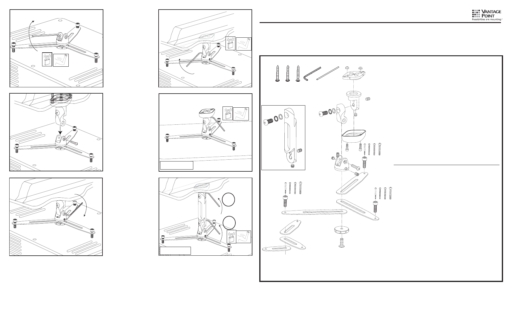
A
#14 X 2” pan head phillips wood screw
3
B
3/16” long arm hex key
1
C
5” steel dowel tool
1
D
1/4” nylock nut (installed at factory)
2
E
projector mount base plate
1
F
projector mount base link
1
G
projector mount end link
1
H
custom button head bolt
1
I
1/2” serrated belleville washer
1
J
bronze thrust bearing
1
K
3/8-16 x 3/4” socket head set screw
2
L
projector mount cover plate
1
M
1/4”-20 x 3/4 socket head cap screw for cover
2
N
projector mount top rotator
1
O
3/8”-16 x 3/8” socket head set screw
2
P
3/8”-16 x 5/8” socket head set screw
1
Q
5/16-18 x 1-1/2” button head cap screw
1
R
projector mount attachment arm Large
3
S
projector mount lower cap
1
T
projector mount retention bolt (installed at factory)
1
U
2.6mm x 40mm pan head phillips screw (projector mounting)
3
V
3.0mm x 40mm pan head phillips screw (projector mounting)
3
W
4.0mm x 40mm pan head phillips screw (projector mounting)
3
X
5.0mm x 40mm pan head phillips screw (projector mounting)
3
Y
projector mount adjustment screw
3
Z
projector mount attachment arm Small
3
PART
DESCRIPTION
QTY
H
custom button head bolt
1
I
1/2” serrated belleville washer
1
J
bronze thrust bearing
1
K
3/8-16 x 3/4” socket head set screw
1
O
3/8”-16 x 3/8” socket head set screw
1
W
6” extension link
1
CGUPM12 ONLY
A
Vis à bois à tête cylindrique Phillips n° 14 x 2 po
3
B
Clé hexagonale à bras long 3/16 po
1
C
Goupille de position en acier 5 po
1
D
Écrou nyloc 1/4 po (installé à l’usine)
2
E
Plaque de base
1
F
Pièce de jonction de base
1
G
Pièce de jonction supérieure
1
H
Boulon à tête ronde sur mesure
1
I
Rondelle Belleville dentée 1/2 po
1
J
Palier de butée en bronze
1
K
Vis de pression à tête creuse 3/8-16 x 3/4 po
2
L
Couvercle de monture
1
M
Vis d’assemblage à tête creuse pour couvercle 1/4 po - 20 x 3/4
2
N
Rotor supérieur
1
O
Vis de pression à tête creuse 3/8-16 x 3/8 po
2
P
Vis de pression à tête creuse 3/8-16 x 5/8 po
1
Q
Vis d’assemblage à tête creuse 5/16-18 x 1 1/2 po
1
R Grande
Bras
de
fi xation
3
S Embout
inférieur
1
T
Boulon de retenue (installé à l’usine)
1
U
Vis à tête cylindrique Phillips 2.6mm x 40mm
3
V
Vis à tête cylindrique Phillips 3.0mm x 40mm
3
W
Vis à tête cylindrique Phillips 4.0mm x 40mm
3
X
Vis à tête cylindrique Phillips 5.0mm x 40mm
3
Y
Vis de réglage
3
Z
Petit Bras de fi xation
3
H
Vis à tête ronde sur mesure
1
I
Rondelle Belleville dentée 1/2 po
1
J
Palier de butée en bronze
1
K
Vis de pression à tête creuse 3/8-16 x 3/4 po
1
O
Vis de pression à tête creuse 3/8 po-16 x 3/8 po
1
W
Longue pièce de jonction 6 po
1
CGUPM12 SEULEMENT
PIÈCE DESCRIPTION
QTÉ
A
B
C
D
E
F
K
H
I J
O
M
L
U
Y
S
R
P
O
N
G
H
I J
K
O
W
Z
V
X
W
Y
Y
T