Vantage Point SATS05 Manuel d'utilisation
Remove dieline before printing, Vantage point products corp, 16 inches (typical) (typical)
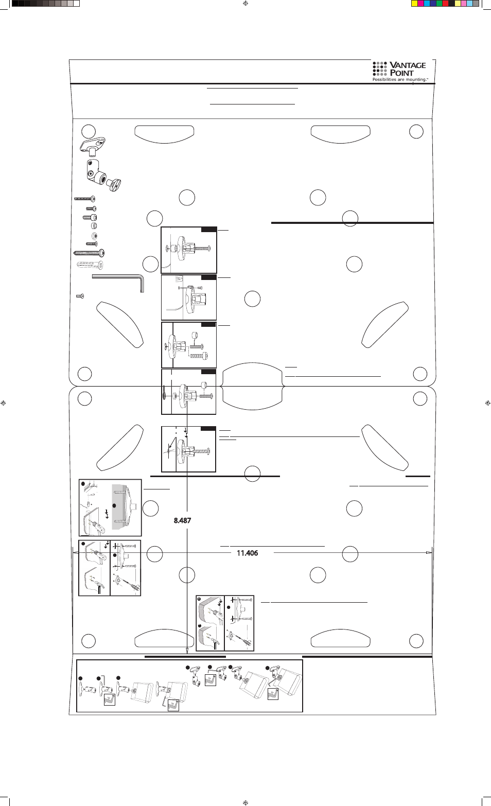
Wall / Ceiling Plate (5)
Link Set (5) assembled at factory
Speaker Post (5)
Maximum Weight Load 8 lbs.
REMOVE DIELINE BEFORE PRINTING
REMOVE DIELINE BEFORE PRINTING
IMPORTANT CONSIDERATIONS PRIOR TO INSTALLATION
Preview all steps before beginning. Should any portion of these instructions be unclear, contact us directly at 800-582-9595 for assistance. Do not attempt to assemble this Vantage Point Mount, if you have any doubts as to its proper assembly and installa-
tion.
CAUTION - Do not exceed maximum weight indicated. Use with heavier than the maximum weight indicated may result in instability causing possible injury. Use of this product for any other purpose unless specified by Vantage Point
Products is not recommended. Think Safety First! This speaker mount is specifically designed for mounting small surround style speakers weighing 8 lbs. or less. Use of this speaker mount for any other purpose unless specified by the manufacturer is not
recommended. Before you begin, separate the speaker mount parts by loosening the set screws with the supplied allen wrench and simply twist apart.
Model SATS05 Satellite Speaker Mount Assembly Instructions
WARRANTY INFORMATION
All Vantage Point Products Corp. products are manufactured to ensure superior quality, performance and durability for a lifetime of use . Warranty covers the product to be free of
defects in materials and workmanship under normal and reasonable use. Vantage Point Products will repair or replace, at our option, any product which proves to be defective upon
our inspection. This warranty will not apply to products that have been lost or damaged by misuse, abuse or accident, altered or repaired in any way or by any person or fi rm other
than specifi ed by us, used in violation of instructions or incorrect assembly nor used in a manner other than specifi ed by us. This warranty is nontransferable to a new owner and may
require proof of purchase. All claims must be directly handled with Vantage Point Products Corp. by calling us at 1-800-582-9595.
GARANTIE
Tous les produits Vantage Point Products sont fabriqués pour assurer une haute qualité, une excellente performance et une grande durabilité. La garantie couvre le produit contre les
vices de matériaux et de fabrication sous des conditions d’utilisation normales et raisonnables. Vantage Point Products réparera ou remplacera, à son choix, tout produit qui s’avère
défectueux suite à son inspection. Cette garantie ne s’applique pas aux produits perdus ou endommagés à cause d’un mauvais usage, d’un abus ou d’un accident, à ceux qui ont
été changés ou réparés d’une manière quelconque par une personne ou une entreprise autre que celles que nous reconnaissons, utilisés contrairement aux instructions ou mal as-
semblés, ou utilisés d’une manière que nous n’avons pas prescrit. Cette garantie n’est pas transférable à un nouveau propriétaire et une preuve d’achat pourrait être exigée.Toutes
les réclamations doivent être adressées directement à Vantage Point Products Corp. en nous appelant au 1-800-582-9595.
Vantage Point Products Corp
P.O. Box 2485 Santa Fe Springs, CA 90670 USA
Tel: 1.800.582.9595 Canada Tel: 905.607.9994
Europe Tel: 31.72.581.6056
Web Site: www.vanptc.com
Email: [email protected]
Step 1. Speaker Post Installation
D
A
Fig. A
TYPE 1
TYPE 1. POST MOUNT BOSE® SPEAKERS Factory Installed Threaded Insert. Most BOSE® satellite speakers will require the use of the 5M x 20mm machine screw
used in combination with the M5 x 1/8” thick plastic washer. (see Fig A). The plastic washer is used as a spacer between the threaded insert and the speaker mount post. It is
critical the M5 spacer is used correctly, otherwise the threaded insert may pull out from the speaker housing. Once proper configuration is determined, secure post to speaker
and Proceed to step 2.
TYPE 1A. POST MOUNT BOSE® LIFESTYLE® or BOSE® ACOUSTIMASS® Speakers
Utilize the M4 x 8mm flat head phillips machine screw as shown in (Fig B.)
Fig. B
J
TYPE 2. POST MOUNT Factory Installed Threaded Insert.
Type 2 instructions is for use with all other speakers with a pre-threaded hole in the back of the speaker.
Check the size of the hole and see if the 8/32” or 1/4” or 20mm machine screw fits inside. Which ever
one fits, put the screw through the speaker post and attach post the the back of the speaker. If screw
does not tighten properly, you will need to use a plastic washer to take up the slack. Once the proper
configuration is determined, secure the post to speaker and Proceed to step 2.
D
C
B
TYPE 2
D
E
B
keyhole
TYPE 3
TYPE 3. POST MOUNT Key Hole Design. If your speaker has a factory key hole design
you will use the 8-32 x 5/8” machine screws in combination with the 8-32 round key hole nut.
Loosely pre-assemble the speaker mount post with 8-32 screw and key hole nut (see fig.)
NOTE: be sure key hole nut is installed with knurled edge toward post.. Engage the key hole
nut into key hole slot as pictured. Put tension on the assembly by gently pulling back on
speaker mount post while tightening the 8-32 screw. The key hole nut will engage on hous-
ing in key hole slot. If the post does not tighten securely against the speaker housing, it will
be necessary to use the M5 plastic washer as a spacer under the head of the 8-32 machine
screw. (see fig.) Once proper configuration is determined secure post to speaker. Proceed to
step (2) If the speaker has a screwed on metal keyhole plate you may remove it and install post
as shown in TYPE 4.
TYPE 4. POST MOUNT No Factory Holes, Wood Cabinet. (For use with speakers weighing 4 lbs or less)
Locate the optimum mounting position for the post and mark through the center of the post for drilling.
NOTE: you do not want to drill or screw into the speaker where you could possibly damage internal
components. Drill a single hole using a 3/32” drill bit. This hole should be drilled no more than 1/2” deep.
You can accomplish this by placing a piece of tape a 1/2” from the end of the drill bit providing you with a
guide. After hole is drilled, mount the post using the #8 x 3/4” self tapping screw. Proceed to step (2)
F
TYPE 4
Ø2.4m x 12.5m
Step 2. Wall Plate Installation
16"
16 inches
(TYPICAL)
(TYPICAL)
16 inches
G
1
3
G
wood
stud
Ø 1/8” x 1-7/8”
Ø 3.1m x 47.65m
montant
de bois
SOLID WOOD OR WOOD STUD - Using a stud finder locate the wood stud or framing member. Using a pick or small drill bit locate the center of the wood stud, be careful doing this as you don’t want to go any
wider than the width of the wall plate (wall plate will cover any extra holes) Using the wall plate as a template mark hole position on mounting surface. NOTE: In wall mounting applications position mounting holes
in a vertical pattern. Drill holes through the drywall and into the wood stud using a 1/8” drill bit. These holes should be drilled no less than 1-7/8” deep. After holes are drilled, mount the wall plate using the #12
x 1-3/4” self tapping screws. Proceed to step (3)
3
G
G
H
1
Ø 5/16” x 1-7/8”
Ø 7.9m x 47.65m
HOLLOW DRYWALL SURFACE - Locate best mounting location in ceiling or wall. Using the wall plate as a template mark hole
position on mounting surface (see fig. 1) NOTE: In wall mounting applications position mounting holes in a vertical pattern. Drill holes
in the drywall using a 5/16” drill bit. Once holes are drilled insert the (4) #12 nylon anchors into the holes making sure anchors
are flush with wall or ceiling surface. With nylon anchors in place, mount the wall plate using the #12 x 1-3/4” self tapping screws
. Proceed to step (3)
SOLID CONCRETE OR HOLLOW BLOCK - Using the wall plate as a template mark hole position on mounting surface (see fig.
1) NOTE: In wall mounting applications position mounting holes in a vertical pattern. (see fig.) Drill holes in the solid concrete or
hollow block using a 5/16” masonry drill bit. Once holes are drilled insert the (4) #12 nylon anchors into the holes making sure
anchor is flush with wall or ceiling surface (see fig. 2) With nylon anchors in place, mount the wall plate using the #12 x 1-3/4”
self tapping screws (see fig. 3) Proceed to step (3)
2
1
3
H
G
G
Ø 5/16” x 1-7/8”
G
Ø 7.9m” x 47.65m”
Step 3. Link Set / Speaker
3
2
1
2
1
4
3
C - 1/4-20 x 7/8” machine screw (5)
F - #8 x 3/4” self tapping screw (5)
G- #12 x 1-3/4” self tapping screw (10)
B - 8-32 x 5/8” machine screw (5)
A - M5 x 20mm machine screw (5)
D - M5 x 1/8” thick plastic washer (5)
H - #12-14 nylon anchor (10)
����������
����������
���������� ����������
����������
����������
���������
���������������
�����������
��������������������
������
������
������
������
�������
������
I - 5/32” allen wrench (1)
E - 8-32 round key hole nut (5)
J - M4 x 8mm flat head machine screw (5)
TYPE 1A
Ø3/32” x 1/2"
Instructions D’installation du Support Enceinte Satellite, Modèle SATS05
CONSIDÉRATIONS IMPORTANTES AVANT L’INSTALLATION
Lisez attentivement toutes les étapes avant de commencer. Si une portion quelconque de ces instructions n’est pas claire, veuillez nous contacter directement au 800-582-9595 pour obtenir de l’aide. N’essayez pas d’assembler ce support Vantage Point si vous
avez des doutes quelconques relativement à son assemblage correct et à sa bonne installation. ATTENTION – Ne dépassez pas le poids maximum indiqué. Tout dépassement du poids maximum indiqué pourrait provoquer une instabilité et possiblement un ac-
cident. L’utilisation de ce produit pour tout autre usage n’est pas recommandée à moins d’être précisée par Vantage Point Product. Pensez à la sécurité avant tout ! L’utilisation de ce support d’enceinte pour tout autre usage n’est pas recommandée à moins d’être
précisée par le fabricant. Avant de commencer, séparez les pièces du support d’enceinte en dévissant les vis avec la clé mâle à six pans fournie et séparez-les en tournant.
(assemblé à l’usine)
Charge Maximum 3.63 Kg
A - vis à métaux M5 x 20mm
F - vis autotaraudeuses #8 x 3/4”
G- vis autotaraudeuses #12 x 1-3/4”
H - cheville en nylon #12-14
I – clé mâle à six pans 5/32 ”
D - rondelle en plastique épais M5 x 1/8”
E - écrou rond en trou de serrure 8-32
B - vis à métaux 8-32 x 5/8”
C - vis à métaux 1/4-20 x 7/8”
J - M5 x 8mm vis à métaux à tête plate
Tige d’enceinte
Plaque murale
Étape 1. Installation de La Tige D’enceinte
TYPE 1. TIGE DE SUPPORT D’ENCEINTES BOSE® Douilles fi letées installées à l’usine. La plupart des enceinte satellite BOSEMD exigent l’utilisation de la
vis à métaux 5M x 20mm utilisée en combinaison avec la rondelle de plastique épaisse M5 x 1/8”. (voir Fig. A). La rondelle en plastique est utilisée comme
une entretoise entre la douille fi letée et la tige de support d’enceinte. Il est essentiel d’utiliser la rondelle d’espacement M5 correctement, autrement la douille
fi letée pourrait sortir du coffret. Une fois la bonne confi guration déterminée, fi xez la tige à l’enceinte et passez à l’étape 2.
TYPE 1A. TIGE DE SUPPORT D’ENCEINTE BOSE® LIFESTYLE® OU ACOUSTIMASS® Utilisez les vis à métaux à tête plate Philips conformément à
l’illustration (Fig. B)
TYPE 2. TIGE DE SUPPORT Douille fi letée installée à l’usine.Les instructions Type 2 sont destinées à toutes les autres enceintes avec des trous préfi letés
à l’arrière de l’enceinte. Vérifi ez la taille du trou et voyez si la vis à métaux 8/32 ” ou 1/4 ” ou 20 mm rentre correctement. Avec celle qui convient, passez la
vis dans la tige de l’enceinte et fi xez la tige à l’arrière de l’enceinte. Si la vis ne serre pas correctement, vous devrez utiliser une rondelle en plastique pour
éliminer le jeu. Une fois la bonne confi guration déterminée, fi xez la tige à l’enceinte et passez à l’étape 2.
TYPE 3. TIGE DE SUPPORT de conception en trou de serrure. Si votre enceinte est de
conception en trou de serrure sortie usine, vous utiliserez des vis à métaux 8-32 x 5/8” avec
les écrous ronds en trou de serrure 8-32. Pré-assemblez, sans serrer, la tige de soutien
de l’enceinte avec la vis 8-32 et l’écrou en trou de serrure (voir fi g.) REMARQUE : Assurez-vous que l’écrou en trou de serrure est installé avec le bord
crénelé vers la tige. Mettez l’écrou en trou de serrure dans l’encoche en trou de serrure comme illustré. Serrez en tirant doucement sur la tige de soutien
de l’enceinte tout en serrant la vis 8-32. L’écrou en trou de serrure entrera dans l’entaille en trou de serrure. Si la tige n’est pas assez serrée contre le cof-
fret, il faudra utiliser la rondelle en plastique comme entretoise sous la tête de la vis à métaux 8-32. (voir fi g.,) Une fois la bonne confi guration déterminée,
fi xez la tige à l’enceinte. Passez à l’étape 2. Si l’enceinte est attachée à une plaque en trou de serrure en métal, vous pouvez la retirer et installer une tige
conformément au TYPE 4.
TYPE 4. TIGE DE SOUTIEN pas de trous usine, coffret bois. (À utiliser avec des enceintes pesant un maximum
de 1,81 kg (4 lb). Trouver la meilleure position d’installation pour la tige et faites une marque qu centre de la tige
pour le perçage à effectuer. REMARQUE : Faites attention de ne pas faire percer ou viser à un endroit de l’enceinte
où vous pourriez endommager les composants internes. Percez un seul trou avec un foret 3/32”. Ce trou ne doit pas
avoir une pro-
fondeur de plus de 1/2” Vous pouvez contrôler sa profondeur en mettant un morceau de
ruban adhésif à
1/2” (1,27 cm) du bout du foret pour vous servir de guide. Après avoir percé le trou, installez
la tige avec les
vis autotaraudeuses #8 x 3/4”. Passez à l’étape (2).
Étape 2. Installation de la plaque murale embase
BOIS MASSIF OU MONTANT EN BOIS – À l’aide d’un localisateur de montant trouvez le montant en bois ou l’élément de charpente. À
l’aide d’une pointe ou d’un petit foret trouvez le centre du montant, en faisant attention de ne pas faire des trous sur une largeur supéri-
eure à celle de la plaque murale (la plaque murale couvrira tous les trous). À l’aide de la plaque murale utilisée comme gabarit, marquez
l’endroit des trous sur la surface de montage. REMARQUE : Pour les applications d’installation murale, placez les trous de montage
à la verticale. Pour percez les trous, traversez la cloison sèche et percez le montant avec un foret 1/8 ”. Ces trous doivent avoir une
profondeur d’au moins 1-7/8 ” (4,76 cm). Après avoir percé les trous, installez la plaque murale avec les vis autotaraudeuses #12 x 1
– 3/4 ”. Passez à l’étape (3).
MUR OU PLAFOND CREUX – Trouvez le meilleur emplacement d’installation au plafond ou au mur. À l’aide de la plaque murale
utilisée comme gabarit marquez l’emplacement du trou sur la surface de montage (voir fi g. 1).REMARQUE : Pour les applica-
tions d’installation murale, placez les trous de montage à la verticale. Percez les trous dans la cloison sèche avec un foret 5/16 ”.
Une fois
les trous percés, insérer les chevilles en nylon (4) # 12 dans les trous en vous
assurant
que les
chevilles sont de niveau avec le mur ou le plafond. Une fois les chevilles de nylon
placées,
installez
la plaque murale.à l’aide des vis autotaraudeuses #12 x1-3/4 ”. Passez à l’étape
(3).
BÉTON PLEIN OU PARPAING CREUX- À l’aide de la plaque murale utilisée comme gabarit, marquez l’emplacement du trou
sur la surface de montage (voir fi g. 1).REMARQUE : Pour les applications d’installation murale, placez les trous de montage à
la verticale. (voir fi g.). Percez les trous dans le béton plein ou le parpaing creux avec un foret 5/16 ”. Percez les trous dans le
béton plein ou le parpaing creux avec un foret 5/16 ”. Une fois les chevilles en nylon en place, installez la plaque murale avec
les vis autotaraudeuses #12 x 1 – 3/4” (voir fi g. 3). Passez à l’étape (3).
Étape 3. Link Set / Enceinte
Wall Mounting / Installation Murale
Ceiling Mounting / Installation au Plafond
SATS05 insert card 10-18-05.indd 1
10/19/2005 8:48:15 AM