Radson Milo H Manuel d'utilisation
Page 4
| 4
InstAllAtIon
Mark out the distance between the brackets as shown in the table and
in the drawings below. Next mark the holes to be drilled and secure the
supports using a suitable fastening for the type of wall. Refit the spring
locking device in its upper fixed position, locate the brackets on the
notches, and then press the top of the radiator towards the wall until
the fixing system engages on the brackets.
The thermostat housing must always be at the bottom, as close as pos-
sible to the floor. The distance between the wall and the radiator is 50
mm, regardless of the model.
A1 + A2
(1) Effective Power: The radiator is equipped with an electronic tem
perature guard that will prevent the surface temperature to reach
excessive values. In such case, the heating element of the radiator
will only be enabled to function during 65% of the full heating cycle,
and as such limiting the heat output to 65% of the nominal power.
This value corresponds to the effective power.
(2) Average power.
A1
* Three fixing systems.
** The support for this model is positioned asymmetrically in order to
leave room for the thermostat.
A2
The vertical radiators (H =>1500) are supplied with safety chains, which
are fitted between the radiator fixing elements and the wall brackets.
Radiators with a height of 1500 mm or above are provided with fasten-
ings at the centre. For hooking and mounting, lift up all the fixing ele-
ments into the mounting position (use the hook supplied to facilitate
this operation), and then push the radiator against the fastenings until
the spring lock emits a click. Check that all the fastenings are securely
locked.
B
Towel rails (HDH 400) are available as an option for vertical radiators
with a width of 400 mm. The HDH 400 consists of two fixed bars. The
distance between the upper bar and the lower bar is 27 cm. The distance
“h” is proposed to be about 10 cm.
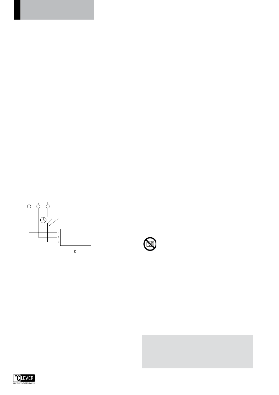
ConneCtIon dIAgrAm
Refer to the wiring diagram when connecting the radiator. The radia-
tor is prepared for a reduction in temperature of 4°C from the built-in
switch or from an external programmer. It is essential to adhere to the
phase and neutral polarities.
Radiator
Brown
Blue
Black
Pilot wire
All electric radiators are class II , and are protected against
water ingress in accordance with IP32. They must not therefore be
earthed. They must be installed only in volume 3 (fig D and E) in bath-
rooms and in other indoor areas. This appliance is equipped with an all-
pole switch with a contact separation of at least 3 mm.
mAIntenAnCe
Use an ordinary liquid cleaner (e.g. washing-up liquid). Do not use abra-
sive products, which could damage the surface of the radiator. Stains
(oil, etc.) may be removed easily with a solvent such as acetone. Surface
scratches may be removed by polishing the surface with fine abrasive
paper.
WhAt Is A mInerAl ComposIte?
It is a material composed of ground minerals embedded in a binder.
ho W to oper Ate YoUr ApplI AnCe
The radiator is turned on by moving the switch, marked I and O, to the
ON position I.
settIng the desIred temperAtUre
• Position the knob (fig. 4) to CONF (Comfort).
• Place a thermometer in the room concerned, at a sufficient distance
from the radiator (on a piece of furniture, for example).
• Move the thermostat knob (fig. 2) close to setting 4 (the light is
illuminated) in fig. 3.
• Watch your thermometer until the desired temperature is reached
(for example 19°C). Once this temperature is achieved, turn the
thermostat knob gently to the left until the light goes out, and no
further.
• Your temperature is then set.
When the thermostat knob is set to *, your appliance will then assure
the protection of your room against frost (about 7°C).
InstAllAtIon WIthoUt A progrAm Control UnIt
In this case, you must not use the pilot wire (black wire). Isolate it inside
the junction box.
The environment knob (fig. 4) must be set to CONF (Comfort).
If you set this knob to Eco, you will obtain between 3 and 4°C less in the
room. For example, if you had set your thermostat to 19°C, you would
obtain 15 or 16°C.
This may be interesting if you wish to maintain a reduced temperature
in a room that is generally unoccupied without disturbing your thermo-
stat. To return to your comfort temperature, it is sufficient to reposition
the knob to CONF.
InstAllAtIon WIth A progrAm Control UnIt
Our appliances are equipped with a supplementary wire (black wire)
known as the ”pilot wire”. This permits your appliance to receive elec-
trical commands from a program control unit. (Ask your electrician for
advice.)
Your radiator is designed to interpret 6 different commands:
1- Comfort - The temperature that you have set on your thermostat
(for example 19°C).
2- Frost-free – Fixed temperature of about 7°C.
3- Stop – The appliance is on stand-by but is not heating.
4- Low-level operation – Between 0 and 15° lower, as preferred.
5- Low-level operation – 2°C lower
6- Low-level operation – 1°C lower
Turn the knob (fig. 4) to PROG (programme) and continue to rotate it to
the right to select the value of the automatic reduction in temperature
(0-15°C). For example 4°C lower at night.
prIorItY fUnCtIons on the progrAm Control UnIt
You require one or more of the radiators to remain in comfort mode. Set
the knob (fig. 4) to CONF*. You require one or more of the radiators to
remain in low-level operation mode. Set the knob (fig. 4) to ECO*
* Commands received by the program control unit are ignored by the
radiator in this case.
loW And verY loW temperAtUre fUnCtIons (fIg. 5)
Selecting one or other of these functions in no way changes either the
output of your appliance or the temperature that you have set for your
room.
low temperature (n)
The surface temperature of the appliance does not exceed 60°C in nor-
mal operation.
very low temperature* (l)
The surface temperature of the appliance does not exceed 45°C in nor-
mal operation.
*Recommended, for example, for the bedroom of a small child, day nurs-
eries, nursery schools, etc.
mIsCellAneoUs
WArnIng - In order to avoid overheating, do not cover the
heater.
“Do not cover” means that the radiator must not be used for
drying clothes, for example, by placing them directly on the
radiator.
The radiator is equipped with a over heat protection device which cuts
the current if the radiator is overheated. It is not possible to reset this
component which means that the whole radiator must be replaced in
such a case.
If the supply cord is damaged, it must be replaced by the manufacturer,
its service agent or similarly qualified persons in order to avoid a hazard.
WARNING: The heater must not be used if the panel is damaged.
This appliance is not intended for use by persons (including children)
with reduced physical, sensory or mental capabilities, or lack of experi-
ence and knowledge, unless they have been given supervision or instruc-
tion concerning use of the appliance by a person responsible for their
safety. Children should be supervised to ensure that they do not play
with the appliance.
Warranty
The warranty is valid for 10 years except for electrical components which
is valid for 2 years. In the event of any problems or repairs, please contact
your supplier.
nB: the rAdIAtor mUst Be InstAlled BY An AUthorIsed
eleCtrICIAn onlY
The radiator must not be mounted below an electrical socket outlet.
If the radiator is installed in a bathroom or shower room, it must be
installed so that it is not possible to reach the switch or thermostat
from the bath or shower.
INSTRUCTIONS
FOR FITTING AND USE