Panasonic VHS Hi-Fi Duplicator AG-6841Hp Manuel d'utilisation
Panasonic мк, Instruction guide
Attention! Le texte de ce document a été détectée automatiquement. Pour consulter le document original, vous pouvez utiliser le mode "Original".
lo^FoDuplicator
AG-ШИ'^
7
Р/AG-ÜÜli
Instruction Guide
Panasonic мк
Professional/lndustrial video LJLH-E=i
Thank you for purchasing the VHS Hi-Fi Duplicator AG-6841 H/AG-6851H. The
AG-6841 H is a dubbing VTR only for use in recording and AG-6851 H is for recording
and playback. They have been designed so that when combined with Cassette Auto
Changer AG-CL78/AG-CL68 (option), automatic loading of up to two cassette tapes can
be performed.
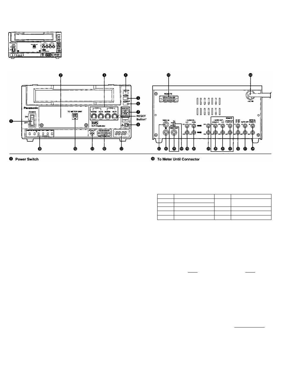
Controls and Their Functions
When set to the ON position, the Eject/Auto OFF Lamp
0
lights if no
cassette is inserted.
0
Peak Meter (Option)
These meters indicate the peak audio input level.
Use the level controls to adjust the input signal as follows:
• Supply a standard signal to the Audio Input Jack. Adjust the level so
that the needle of the level meter indicates as below.
Normal Audio: Hi-Fi Position
Hi-Fi Audio; Hi-Fi Position
• Supply normal sound and check that the needle of the level meter does
not exceed the “0" position.
• Dolby NR* Level: The Dolby NR level is located at the “-6" position.
0
Audio Input Level Control (CH1/CH2)
These controls are used to adjust the audio input level while monitoring
the Audio Meter AG-AM10 (option) or Audio Meter Unit AG-AM20
(option).
O Tape Run Lamp
Lights: During FF or REW mode.
Flashes: During cassette tape with CTL signal is running.
0 Record Lamp
Lights: Recording mode
Flashes: No signal is input in the recording mode, or when the "Rec
Auto Off” (internal switch) is turned ON.
0
Eject/Auto OFF Lamp
Lights:
No cassette is inserted
Flashes: Malfunction has occured to the tape transport system. The
unit will not operate.
0
Mode Indicator Lamps
VIDEO AGC: Lights when the “Video AGO (Automatic Gain Control)” is
turned ON.
Hi-Fi:
Lights when the “Hi-Fi Audio Recording" is turned ON.
LIMITER:
Lights when the “Audio Limited’ is turned ON.
DOLBY NR; Lights when the “Dolby NR” is turned ON.
0
Eject Button
0
Test Terminals
An oscilloscope can be connected to these terminals for confirmation of
Video and Hi-Fi Audio RF output during playback, as well as Phase
Generator and Drop Out Compensation.
"RESET Button
This button is located inside the front panel. Press this button to reset the
hour meter to “0".
* Dolby noise reduction manufactured under license from Dobly Laboratories Licensing Corporation.
* “DOLBY" and the double-D symbol □□ are trademarks of Dolby Laboratories Licensing Corporation.
To confirm the audio recording meter level, connect the Audio Meter Unit
AG-AM20 (option).
Remote Control Connector
Exclusively for the Remote Controller AG-A11 (option).
To Changer Connector
Connect the VTR Connector of the Cassette Auto Changer AG-CL78 or
AG-CL68 (option).
Pin No.
Signal
Pin No.
Signal
1
+20 V Output
6
AUT OFF Output
2
+5 V Output
3
GND
7
EJECT SWiD
4
CAS IN Output
8
EJECT SW (2)
5
CAS OUT Output
9
START Output
Hour Meter
Indicates the head rotation time by each 10-hour unit. (It can be
displayed up to 30,000 hours.)
AC Power Cord
3-prong grounded type. Do not defeat its purpose.
Video Input Connector (BNC type)
Video Input Connector (Loop through type)
This connector can bridge the Video Input Connector ©.
Remote Control Connector (34P)
Connect to the Remote Controller AG-A600 (option).
Pin No.
1
10-11
12
13-17
18
Signal
REC SWITCH
PLAY SWITCH
FF SWITCH
REW SWITCH
STOP SWITCH
PAUSE SWITCH
CASSETTE IN
GND
GND
REEL PULSE
Pin No.
19-20
21
22
23
24
25
26
27
28
29
30-33
34
Signal
EJECT SWITCH
REC HOLD
PLAY HOLD
FF HOLD
REW HOLD
STOP HOLD
PAUSE HOLD
+12 V (max. 100 mA|
’ HOLD signals are output by open collector circuits. Therefore, user's
remote controller for these pins should be designed as open collector
output circuits or Transistor Transistor Logic (TTL) level.
’ Number 34 pin (+12 V) should be used only for our remote controller
AG-A600.
Printed in Japan
VQT7949
S109eH100
Document Outline
- Instruction Guide
- A
- A
- WARNING:
- TO REDUCE THE RISK OF FIRE OR SHOCK HAZARD, DO NOT EXPOSE THIS EQUIPMENT TO RAIN OR MOISTURE.
- AG-AM10/AG-AM20 (Opiton)