Retrofit installation, 12 - insert and secure blower assembly – Greenheck SP-110L-VG and SP-80L-VG Lighted Multi-Speed Ceiling Exhaust Fan (IOM) Manuel d'utilisation
Page 10
1
2
3
1
2
3
1
2
3
4
If ceiling repairs are needed,
place Mask in Housing after
Blower Assembly is secured.
See New Construction
Installation Step 6. Remove
Mask before installing Grille.
Screws from Parts Bag
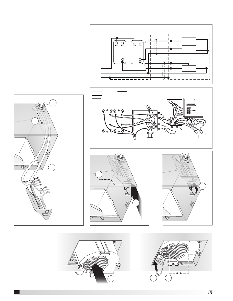
12 - Insert and Secure
Blower Assembly
2
1
4
5
6
3
2
1
4
5
6
3
2
1
4
5
6
3
Screw from
Parts Bag
Connect wires
Fan
Light
Screw set
aside in
Step 6
Attach cable
clamps to
Knockout Plate.
Knockout Plate
mounts to inside
of Housing and
maybe oriented
as desired.
LINE
IN
GRD
GRD
WHT
WHT
WHT
WHT
WHT
WHT
BLK
BLK
BLK
BLU
BLK
RED
RED (Rated Level)
RED
RED
BLK*
MASTER
ON/OFF
SWITCH
FAN
MODE
SELECT
SWITCH
FAN
LIGHT
LIGHT
NIGHT
LIGHT
NIGHT
LIGHT
UNIT
SWITCH BOX
(* Adjustable Level)
(2) 2-FUNCTION
CONTROLS
KNOCKOUT
PLATE
FAN
RECEPTACLE
LIGHT
RECEPTACLE
LIGHT
RECEPTACLE
WIRES
FAN
RECEPTACLE
WIRES
(2) 2-FUNCTION CONTROLS
(purchase separately)
120 VAC
LINE IN
MODE
SELECT
MASTER
ON/OFF
SWITCH
FAN
SWITCH
BOX
LIGHT
NIGHT
LIGHT
BLACK
WHITE
BLUE
RED
GROUND
(green or bare)
Retrofit Installation
11 - Install Knockout Plate,
Connect Wires and Install
Wiring Panel
• Use proper UL-approved connectors
to secure wiring to the Knockout Plate
provided in Parts Bag.
• Connect wires as shown in wiring
diagram.
• Do not use a dimmer switch to
operate the light.
10
SP Ceiling Exhaust Fans
®