Ps__sf flyware - en, Eyebolt installation – Yorkville Sound PS15S 15" Parasource Powered Subwoofer (1000W) Manuel d'utilisation
Page 10
weight of cabinet only
PS12SF
4 Top
3/8-16
weight of cabinet only
PS15SF
4 Top
3/8-16
PS18SF
4 Side
weight of cabinet only
3/8-16
DOC-flyware-PS__S-00-1v1. • July 22/2020
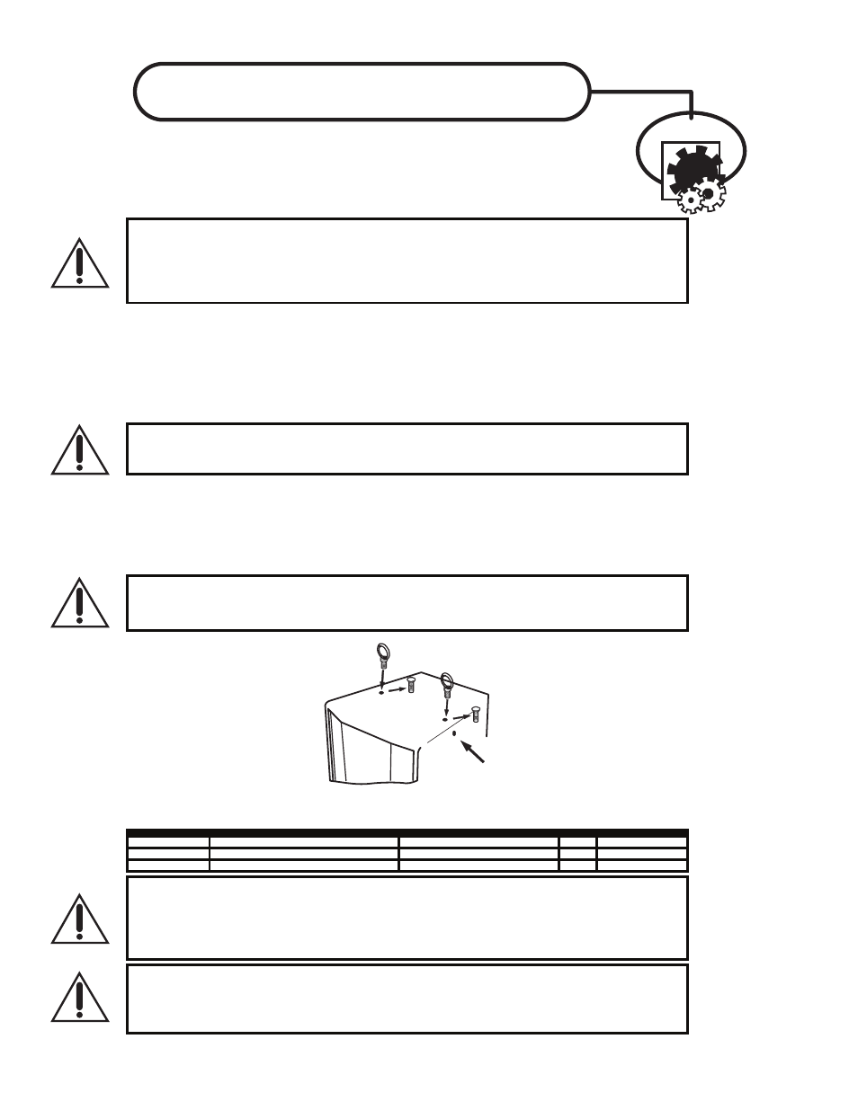
EYEBOLT INSTALLATION
Remove
Flat-Head Bolt
and
replace with
Forged Shoulder Eyebolt!
DO NOT
Remove
Flat-Head Bolts
on the Side of Cabinet/s.
1. DESCRIPTION
Many of the popular models in the Yorkville speaker cabinet line are now equipped with flying
hardware for overhead suspension applications. Depending on the model, two or more internal
braces have been provided for rigging purposes. Each brace contains two bolt holes and provides
center-of-gravity fly-points for use with in-line or angular loads. Many of the models will support
additional suspended cabinets according to their specified working load limits.
IMPORTANT!!
THE RIGGING OF LOUDSPEAKER SYSTEMS IS AN EXTREMELY SERIOUS MATTER. OVERHEAD RIGGING REQUIRES EXTENSIVE
EXPERIENCE, INCLUDING (BUT NOT LIMITED TO) CALCULATING WORKING LOAD LIMITS, HARDWARE INSTALLATION, AND
PERIODIC SAFETY INSPECTION OF ALL HARDWARE AND CABINETRY. IF YOU LACK THESE QUALIFICATIONS, DO NOT ATTEMPT
THE INSTALLATION YOURSELF, BUT INSTEAD USE A PROFESSIONAL STRUCTURAL RIGGER. IMPROPER INSTALLATION CAN
RESULT IN BODILY INJURY OR DEATH. CONSULT A STRUCTURAL ENGINEER TO CALCULATE ADDED LOADS FOR A BUILDING.
STRUCTURAL REINFORCEMENT MAY BE NECESSARY TO INSURE A SAFE INSTALLATION.
2. REQUIRED TOOLS
4.5mm (7/32”) Hex Wrench
Thread lock adhesive (Removable Type)
3. EYEBOLT INSTALLATION
a) Using a 4.5mm (7/32”) hex wrench, remove the flat head bolts from the top or bottom of the speaker enclosure
to expose the tapped holes (on TX models, the flat head bolts are located within the track rails), as shown below.
Be sure to keep these handy as they will be needed to seal the cabinet after the eyebolts are removed.
IMPORTANT!!
USE ONLY LOAD RATED FORGED EYEBOLTS. THESE MAY BE PURCHASED THROUGH YORKVILLE SOUND OR ATM FLY-WARE™.
TO INSURE CABINET-BRACING STRENGTH, MAKE SURE ALL FLY-POINTS ARE SECURED WITH EITHER AN EYEBOLT OR FLAT
HEAD HEX BOLT.
b) Place a drop of thread-lock adhesive on the threads of the eyebolt and insert one into exposed hole. Tighten each
eyebolt by hand until its fits snugly against the cabinet. Further tighten each eyebolt by rotating it another half turn. Be
sure to insert eyebolts in the threaded hole directly in-line with the suspension cable. Always follow the eyebolt
manufacturers installation and use instructions.
c) Suspend each cabinet according to working load calculations and practices recommended by the rigging
hardware manufacturer.
IMPORTANT!!
ON MODELS WITH ONLY TWO TOP SUSPENSION POINTS THE SUPPLIED PULL BACK AT THE REAR OF THE BOTTOM
CENTER PANEL OF THE CABINET IS NOT TO BE USED AS A SUSPENSION POINT. THIS POINT TO BE USED FOR PULL BACK
PURPOSES ONLY.
IMPORTANT!!
READ ALL ENCLOSED INSTRUCTIONS ABOUT PROPER USE OF HARDWARE. TO INSURE PROPER
INSTALLATION, FOR TECHNICAL INFORMATION ON SUSPENSION TECHNIQUES AND EXTERIOR ACCESSORY INFORMATION
WE SUGGEST CALLING ATM FLY-WARES TECHNICAL SERVICES IN THE UNITED STATES AT (310)639-8282 MONDAY THROUGH
FRIDAY FROM 9 AM TO 6 PM (PST) OR FAX AT (310)639-8284. YORKVILLE SOUND MAKES NO CLAIMS AS TO THE SAFETY OF
THE ENCLOSURES IF RECOMMENDED LOAD LIMITS AND HARDWARE ARE NOT STRICTLY ADHERED TO. NOR DOES IT MAKE
ANY SAFETY CLAIMS TO THE RESULTANT INSTALLATION.
IMPORTANT!!
TRACK RAILINGS: UNITS THAT INCORPORATE THE TRACK RAILING SYSTEM HAVE THE SAME WORKING LOAD
LIMITS AS THEY DO WHEN THEY ARE USED WITH EYEBOLTS. THESE RATINGS MAY BE LIMITED AND BASED ON THE RATINGS
OF THE TRACK FITTINGS THEMSELVES. PLEASE ENSURE THAT THE RATING OF THE CERTIFIED TRACK FITTINGS EXCEEDS
NECESSARY WORKING LOAD LIMITS
.
4. WORKING LOAD LIMITS
Specified working load limits have been determined for the enclosure as follows: