An n, An 2, Schéma de connexions interne rkm 720 a n 2 – REMKO RKM 610 Manuel d'utilisation
Page 15
15
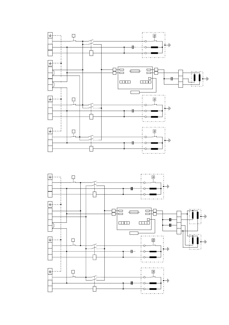
Schéma de connexions interne RKM 710 / RKM 713
A
N
2
sw
bl
ws
C
S
R
A
A
N
N
CM 1
C1
TS 2
TS 1
P
KCM1
bn
gn/ge
sw
or
ws
rt
A
N
2
sw
bl
ws
C
S
R
CM 2
C2
TS 3
P
KCM2
bn
sw
or
ws
rt
bn
bn
ws
ws
ws
Kompressor
Innengerät 1
Kompressor
Innengerät 2
TS 5
1
2
1
2
JP
1
JP
2
JP
3
JP
4
JP
5
JP
6
JP
7
JP
8
Sicherung
3 A / 250 V
TS 6
TS 6
Winterregelung
P1
Sensor
VM
C3
rt
ws
bn
sw
ws
Ventilator
Außenteil
A
N
2
sw
bl
ws
C
S
R
CM 3
C3
TS 4
P
KCM3
bn
sw
or
ws
rt
Kompressor
Innengerät 3
Borne plate
unité inté-
rieure
circuit A
Borne plate
unité intérieure
circuit B
Conduite
d’alimentation
secteur
Borne plate
unité intérieure
circuit C
Schéma de connexions interne RKM 720
A
N
2
sw
bl
ws
C
S
R
A
A
N
N
CM 1
C1
TS 2
TS 1
P
KCM1
bn
gn/ge
sw
or
ws
rt
A
N
2
TS 3
P
KCM2
bn
sw
or
ws
rt
bn
bn
ws
ws
ws
Kompressor
Innengerät 1
sw
bl
ws
C
S
R
CM 2
C2
Kompressor
Innengerät 2
TS 5
1
2
1
2
JP
1
JP
2
JP
3
JP
4
JP
5
JP
6
JP
7
JP
8
Sicherung
3 A / 250 V
TS 6
TS 6
Winterregelung
P1
Sensor
VM1
C4
rt
ws
bn
sw
ws
Ventilator 1
Außenteil
A
N
2
sw
bl
ws
C
S
R
CM 3
C3
TS 4
P
KCM3
bn
sw
or
ws
rt
Kompressor
Innengerät 3
C5
bn
Ventilator 2
Außenteil
VM2
Borne plate
unité inté-
rieure
circuit A
Borne plate
unité intérieure
circuit B
Conduite
d’alimentation
secteur
Borne plate
unité intérieure
circuit C
Compresseur
unité intérieure 1
Réglage hiver
Ventilateur
Fusible
Capteur
bl
bc
nr
Compresseur
unité intérieure 2
ve/ja
no
bc
bn
bn
bn
or
bc
no
bn
or
no
bn
or
ro
ro
bc
ro
bc
bl
bc
nr
bl
bc
nr
Compresseur
unité intérieure 3
Compresseur
unité intérieure 1
Réglage hiver
Ventilateur
1
Fusible
Capteur
bl
bc
nr
Compresseur
unité intérieure 2
no
bc
ve/ja
bn
bn
bn
or
bc
no
bn
or
no
bn
or
ro
ro
bc
ro
bc
bl
bc
nr
bl
bc
nr
Compresseur
unité intérieure 3
Ventilateur
2
bn
bn
nr
bc
bc
bc
ro
bc
bc
ro
bc
b
bc
nr