CIRCUTOR CVM144 Series Manuel d'utilisation
Page 15
Advertising
----- Appareil de mesure CVM-
144
-------- M-981 701 --- Page Nº 14
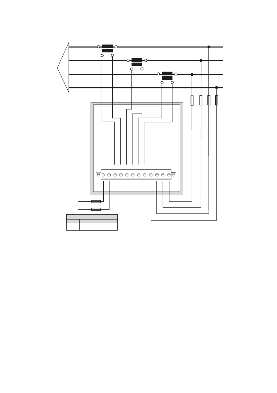
4.4.- Schéma de connexion CVM-144 :
a.- Réseau triphasé - 4 fils (basse tension) :
S1
P1
S2
P2
L1
L2
L3
N
S1
P1
S2
P2
S1
P1
S2
P2
N
VL3
VL2
VL1
1 2 3 4 5 6 7 8 9 10 11 12
ALIMENTATION C.A.
Alimentation (Modèle SDC)
Borne
Description
+ V c.c.
- V c.c.
1
2
Advertising