KITCHENAID W10153187A Manuel d'utilisation
Ventilateur KITCHENAID
Advertising
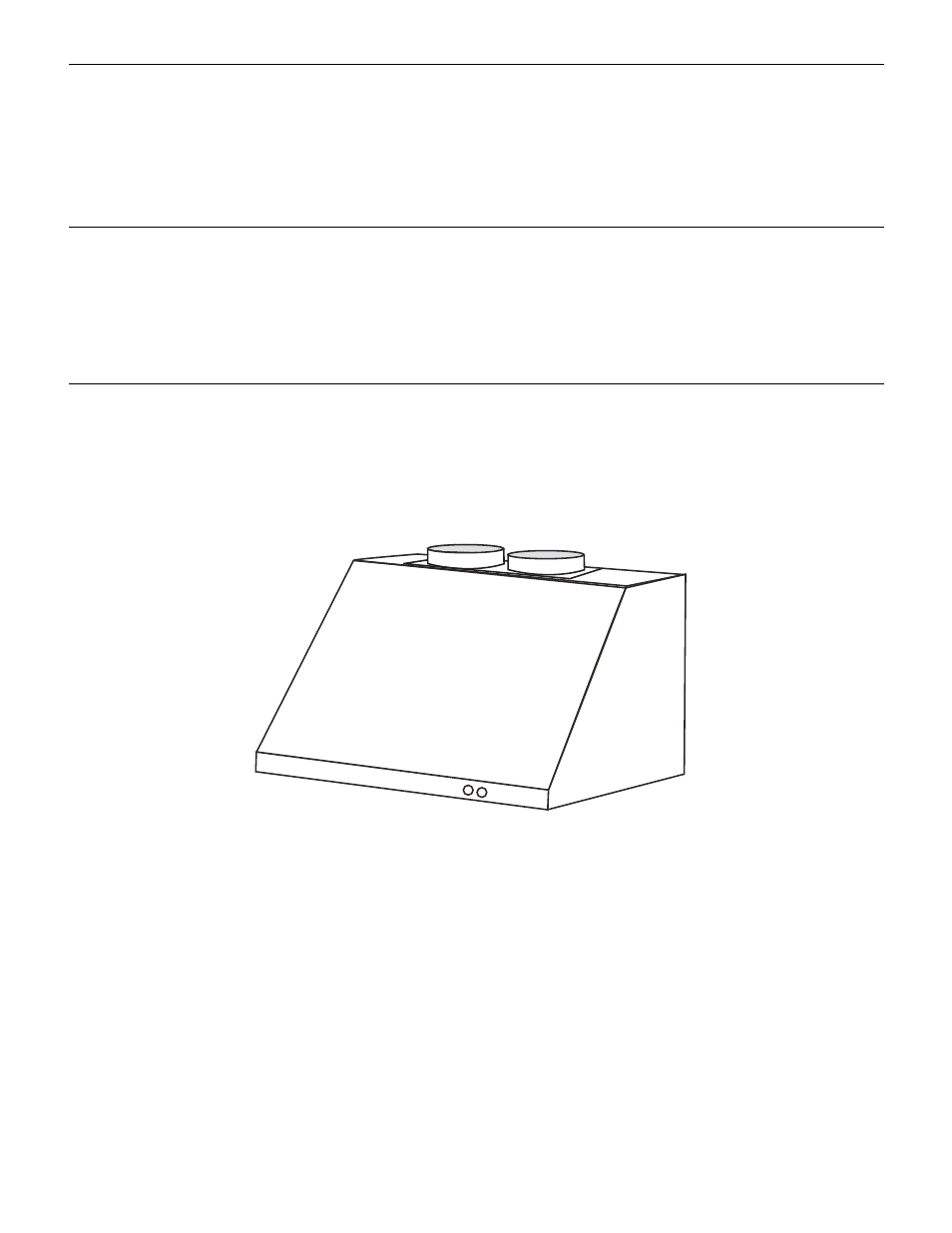
30" (76.2 CM), 36" (91.4 CM) AND 48" (121.9 CM)
WALL-MOUNT CANOPY GRILL VENT HOOD
Suitable for Use in Damp Locations
Installation Instructions and Use & Care Guide
HOTTE DE CUISINIÈRE POUR MONTAGE MURAL
30" (76,2 CM), 36" (91,4 CM), ET 48" (121,9 CM)
Pour une utilisation en milieu humide
Instructions d’installation et Guide d’utilisation et d’entretien
Table of Contents/Table des matières............................................................................. 2
IMPORTANT: READ AND SAVE THESE INSTRUCTIONS.
FOR RESIDENTIAL USE ONLY.
IMPORTANT : LIRE ET CONSERVER CES INSTRUCTIONS.
POUR UTILISATION RÉSIDENTIELLE UNIQUEMENT.
W10153187
Advertising