MEDC XB15 Manuel d'utilisation
Page 3
Cable Termination
CAUTION: Before removing the cover assembly, ensure that the power to the unit is isolated.
Unscrew the set screw in the flange of the cover 3 turns minimum (2.0mm A/F hexagon key). Unscrew
and remove the cover and lens assembly using the spanner supplied to gain acess to the inside of the
unit. Unscrew the 2 off thumbscrews and carefull lift the PCB assembly clear of the mounting pillars to
gain access to the terminals.
Cable termination should be in accordance with specifications applying to the required application. MEDC
recommends that all cables and cores should be correctly identified. Please refer to the wiring diagram
provided in this manual or supplied with the product if specific qiring has been specified.
Ensure that only the correct listed or certified cable glands are used and that the assembly is shrouded
and correctly earthed. For supply connections, use minimum 90°C rated wire.
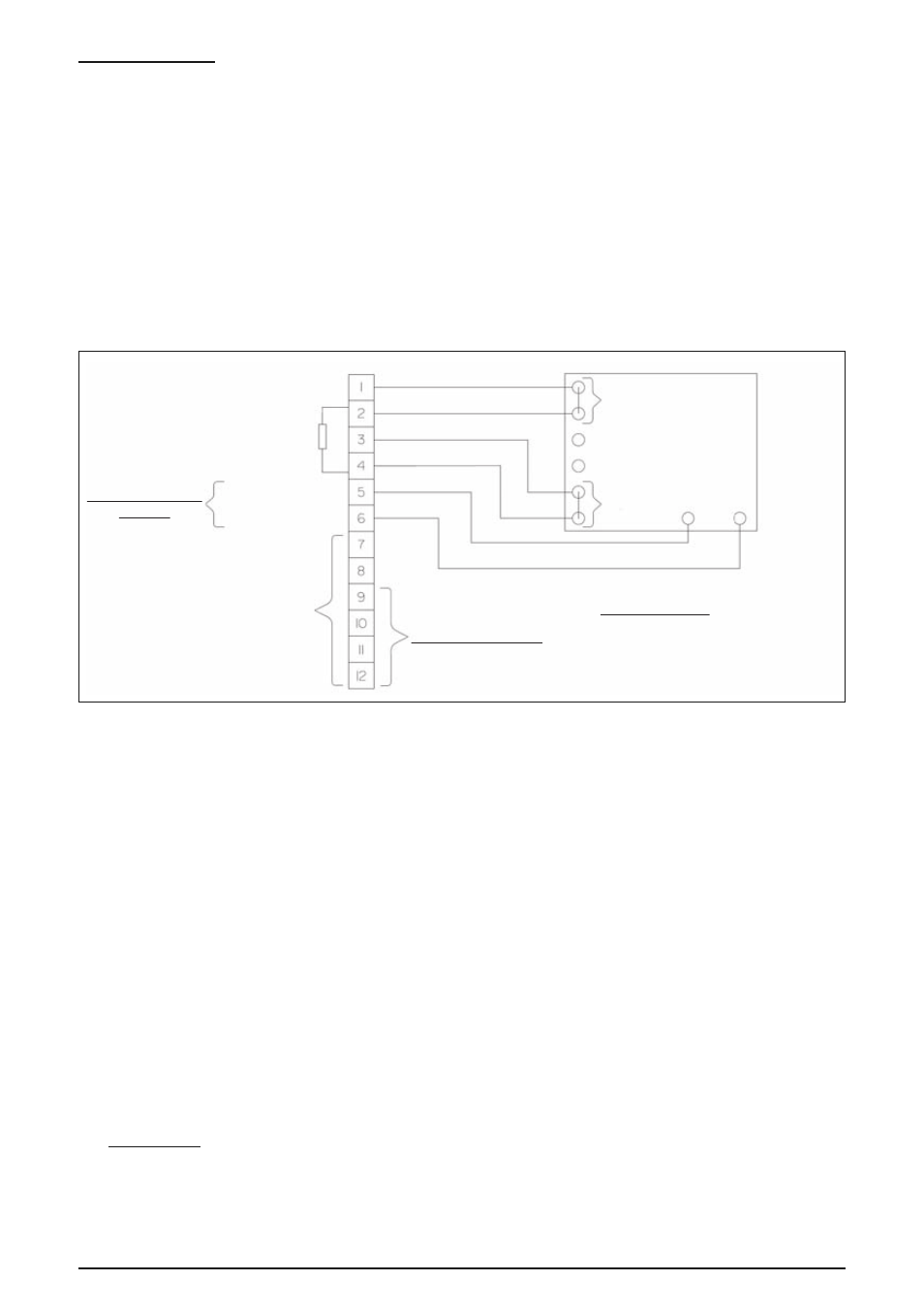
WIRING DETAIL
All cable glands should be of an equivalent NEMA/IP rating to that of the unit and integrated with the
unit such that this rating is maintained.
The internal earth terminal, where fitted, must be used for the equipment grounding connection.
Once termination is complete, carefully replace the PCB assembly onto the mounting pillars and fully
tighten the thumbscrews. Take care not to over tighten. Replace the cover and lens assembly, ensuring the
cover is screwed down fully and that the cover seal is correctly seated during re-assembly. There should
be a maximum gap of 1/128” (0.2mm) between the faces of the cover and enclosure to ensure correct
o-ring compression. Re-tighten the set screw (2.0mm A/F hexagon key) in the cover flange to secure the
cover into position.
Warning Statements
i)
Seal all conduit entries
ii) Fire Alarm Device do not paint
iii) To avoid electrostatic build up, clean enclosure exterior with a damp cloth
iv) Do not open when energized
v) Do not open when an explosive atmosphere may be present
vi) Not to be used as a visual public mode alarm notification appliance* applicable to UL version only
vii) Flameproof joint between cover and enclosure - threaded type with a minimum of five full thread
engagement for a minimum length of 10mm
3.0 OPERATION
The operating voltage of the unit is stated on the unit label. The unit can be powered directly or initiated
via a 24Vdc relay if requested when ordered.
REMOTE INITIATE
OPTION
POWER IN ( +VE/L )
POWER OUT
POWER IN
POWER OUT
( +VE/L )
( +VE/L )
( -VE/N )
( -VE/N )
( -VE/N )
INIT .
INIT .
RI
DC RED / AC BROWN
DC RED / AC BROWN
DC BLACK / AC BLUE
DC BLACK / AC BLUE
RED
BLACK
T1. T3
T2. T4
T5
T6
UNUSED
TERMINALS
(DM VERSION ONLY)
GENERAL NOTES:
1. EARTH TO BE CONNECTED TO STUD
IN HOUSING
2. RI - OPTIONAL RESISTOR
470Ω MINIMUM, 2.5W MINIMUM
© MEDC 2015
02/15