Kichler 43402 Manuel d'utilisation
Luminaires Kichler
14) Visser un second écrou hexagonal de manière à ce qu’il touche presque
le premier. Visser ensuite le tube fileté sur la patte de fixation, en le
faisant dépasser et en dirigeant la partie filetée des vis vers la boîte de
jonction. Visser un troisième écrou hexagonal sur l’extrémité du tube
fileté sortant de l’arrière de la sangle de montage. Visser un troisième
écrou hexagonal sur l’extrémité du tube fileté sortant de l’arrière de la
sangle de montage.
15) Connecter la patte de fixation à la boîte de jonction.
16) Dévisser la bague filetée du collier-écrou. Passer le cache sur le
collier-écrou. Environ la moitié de filetage extérieur de celui-ci doit être
apparent. Fixer le collier-écrou en faisant pivoter l’assemblage vers le
haut ou vers le bas. Enlever le cache.
17) Une fois bien positionné, serrer les deux écrous hexagonaux, supérieur
et inférieur, contre le dessous et le dessus de la sangle de montage.
18) Glisser le cache sur le collier-écrou et enfiler sur la bague filetée.
Attacher la chaine (avec l’assemblage connecté) au bas du collier-
écrou. Dévisser la bague filetée et laisser glisser le cache et la bague
filetée.
19) Entrelacer le fil électrque et le fil de mise á la terre et faire passer le tout
dans les anneaux de la chaîne en espaçant au maximum de 3 po.
Passer le fil dans la bague filetée, le cache, le collier-écrou, le tube
fileté et la boîte de jonction.
20) Avec l’attache-fil (qui n’est pas fourni), connecter le fil de mise á la terre
au fil d’alimentation noir ou á celui qui est blanc.
21) Connecter les fils (connecteurs non fournis). Se reporter au tableau
ci-dessous pour faire les connexions.
22) Placer le cache au plafond.
23) Fixer le cache en serrant la bague filetée sur le collier-écrou.
24) Passer le verre par-dessus la douille. Serrer l’anneau de la douille sur la
douille. (NE PAS serrer avec excès).
1) Thread end of long threaded pipe in to coupling on top of fixture body.
2) Slip tube down over long threaded pipe.
3) Slip check ring then cup over end of threaded pipe.
4) Thread hex coupling on to end of threaded pipe protruding from inside cup.
5) Insert peg on bottom of top arm into hole in bottom arm.
6) Align hole in top of top arm with hole in cup at top of center tube.
7) From inside cup, thread ball stud through hole in cup and into hole in top of arm.
Tighten ball stud to secure arm in place.
8) Repeat steps 4-6 for remaining arms.
9) Lower end of threaded pipe down into cup on top of center tube. Screw end of
threaded pipe into hex coupling inside cup.
10) Pass hole in top trim down over end of threaded pipe and set top trim on top of
cup.
11) Screw loop onto end of threaded pipe protruding from top of top trim.
12) TURN OFF POWER.
IMPORTANT: Before you start, NEVER attempt any work without
shutting off the electricity until the work is done.
a) Go to the main fuse, or circuit breaker, box in your home. Place
the main power switch in the “OFF” position.
b) Unscrew the fuse(s), or switch “OFF” the circuit breaker switch(s),
that control the power to the fixture or room that you are working on.
c) Place the wall switch in the “OFF” position. If the fixture to be
replaced has a switch or pull chain, place those in the “OFF”
position.
13) Take threaded pipe from parts bag and screw in screw collar loop a
minimum of 6 mm (1/4”). Lock into place with hexnut.
14) Run another hexnut down threaded pipe almost touching first hexnut.
Now screw threaded pipe into mounting strap. Mounting strap must be
positioned with extruded thread faced into outlet box. Threaded pipe
must protrude out the back of mounting strap. Screw third hexnut onto
end of threaded pipe protruding from back of mounting strap.
15) Connect mounting strap to outlet box.
16) Unscrew the threaded ring from screw collar loop. Take canopy and
pass over screw collar loop. Approximately one half of the screw collar
loop exterior threads should be exposed. Adjust screw collar loop by
turning assembly up or down in mounting strap. Remove canopy.
17) After desired position is found, tighten both top and bottom hexnuts up
against the bottom and top of the mounting strap.
18) Slip canopy over screw collar loop and thread on threaded ring. Attach
chain (with fixture connected) to bottom of screw collar loop. Unscrew
threaded ring, let canopy and threaded ring slip down.
19) Weave electrical wire and ground wire through chain links no more than
3 inches apart. Pass wire through threaded ring, canopy, screw collar
loop, threaded pipe and into outlet box.
20) Connect fixture ground wire to outlet box ground wire with wire connector.
(Not provided.) Never connect ground wire to black or white power
supply wire.
21) Make wire connections (connectors not provided). Reference chart
below for correct connections and wire accordingly.
22) Raise canopy to ceiling.
23) Secure canopy in place by tightening threaded ring onto screw collar
loop.
24) Set glass down over socket. Thread socket ring onto socket. (DO NOT
over tighten.)
1) Serrer l’extrémité du long tube fileté dans l’accouplement sur la partie
supérieure du luminaire.
2) Passer le tube sur le long tube fileté.
3) Glisser la bague de retenue puis la coupelle sur l’extrémité du tube fileté.
4) Visser l’accouplement hexagonal sur l’extrémité du tube fileté sortant de
la coupelle interne.
5) Placer la cheville sur la partie inférieure du bras supérieur dans le trou
situé dans le bras inférieur.
6) Aligner le trou situé sur la partie supérieure du bras supérieur au trou
dans la coupelle en haut du tube central.
7) Depuis la coupelle intérieure, visser le goujon à bille par le trou dans la
coupe et dans le trou situé dans la partie supérieure du bras. Serrer le
goujon à bille pour fixer le bras.
8) Répéter les étapes 4 et 6 pour les bras restants.
9) Abaisser l’extrémité du tube long fileté dans la coupelle sur la partie
supérieure du tube central. Visser l’extrémité du tube fileté dans
l’accouplement hexagonal à l’intérieur de la coupelle.
10) Passer le trou dans la garniture supérieure l’extrémité du tube fileté et
placer la garniture supérieure sur la partie supérieure de la coupelle.
11) Visser la boucle sur l’extrémité du tube fileté sortant de la partie
supérieure de la garniture supérieure.
12) COUPER LE COURANT.
IMPORTANT: TOUJOURS couper l’électricité avant de commencer le
travail.
a) Localiser le coffret à fusibles ou le disjoncteur du domicile. Mettre
l’interrupteur principal en position d’Arrêt.
b) Dévisser le ou les fusibles (ou mettre le disjoncteur sur Arrêt) qui
contrôlent l’alimentation vers le luminaire ou la pièce dans
laquelle le travail est effectué.
c) Mettre l’interrupteur mural en position d’Arrêt. Si le luminaire à
remplacer est doté d’un interrupteur ou d’une chaîne connectée à
l‘interrupteur, placer ces éléments en position d’Arrêt.
13) Visser le tube fileté (qui se trouve avec les pièces détachées) dans le
collier-écrou, sur une longueur minimum de 6 mm (1/4 po). Fixer avec
un écrou hexagonal.
Date Issued: 8/26/11
IS-43402-CB
Connect Black or
Red Supply Wire to:
Connect
White Supply Wire to:
Black
White
*Parallel cord (round & smooth)
*Parallel cord (square & ridged)
Clear, Brown, Gold or Black
without tracer
Clear, Brown, Gold or Black
with tracer
Insulated wire (other than green)
with copper conductor
Insulated wire (other than green)
with silver conductor
*Note: When parallel wires (SPT I & SPT II)
are used. The neutral wire is square shaped
or ridged and the other wire will be round in
shape or smooth (see illus.)
Neutral Wire
INSTRUCTIONS
For Assembling and Installing Fixtures in Canada
Pour L’assemblage et L’installation Au Canada
Connecter le fil noir ou
rouge de la boite
Connecter le fil blanc de la boîte
A Noir
A Blanc
*Au cordon parallèle (rond et lisse)
*Au cordon parallele (à angles droits el strié)
Au bransparent, doré, marron, ou
noir sans fil distinctif
Au transparent, doré, marron, ou
noir avec un til distinctif
Fil isolé (sauf fil vert) avec
conducteur en cuivre
Fil isolé (sauf fil vert) avec
conducteur en argent
*Remarque: Avec emploi d’un fil paralléle
(SPT I et SPT II). Le fil neutre est á angles
droits ou strié et l’autre fil doit étre rond ou
lisse (Voir le schéma).
Fil Neutre
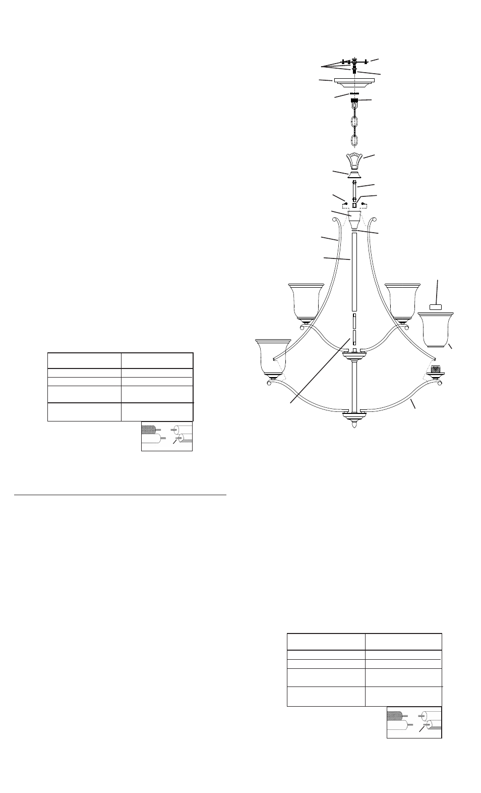
MOUNTING STRAP
PATTE DE FIXATION
HEXNUT
ECROU HEXAGONAL
THREADED PIPE
TUBE FILETÉ
SCREW COLLAR LOOP
COLLIER-ÉCROU
CANOPY
CACHE
THREADED RING
BAGUE FILETÉE
LOOP
ANNEAU
GLASS
VERRE
SOCKET RING
ANNEAU DE LA DOUILLE
THREADED PIPE
TUBE FILETÉ
TOP ARM
BRAS SUPÉRIEUR
CHECK RING
BAGUE DE RETENUE
LONG THREADED PIPE
LONG TUBE FILETÉ
TUBE
TUBE
CUP
COUPELLE
TOP TRIM
GARNITURE SUPÉRIEURE
BALL STUD
GOUJON À BILLE
HEX COUPLING
ACCOUPLEMENT
HEXAGONAL
BOTTOM ARM
BRAS INFÉRIEUR