Kichler 43628 Manuel d'utilisation
Luminaires Kichler
NOTE: Height of fixture must be adjusted before fixture is mounted to ceiling.
1) For each pendant, loosen threaded stud on strain relief on canopy. Insert cord into
hole in strain relief and up into canopy.
2) To adjust the length of the cord to achieve the desired height of the mounted
fixture: Carefully pull cord up into canopy to shorten the height of fixture or
carefully pull cord down to lengthen the height of fixture. When desired height
is achieved, tighten threaded stud on strain relief. Tie cord protruding from inside
canopy in knot and tighten knot securely.
3) TURN OFF POWER.
IMPORTANT: Before you start, NEVER attempt any work without shutting off the
electricity until the work is done.
a) Go to the main fuse, or circuit breaker, box in your home. Place the main
power switch in the “OFF” position.
b) Unscrew the fuse(s), or switch “OFF” the circuit breaker switch(s), that control
the power to the fixture or room that you are working on.
c) Place the wall switch in the “OFF” position. If the fixture
to be replaced has a switch or pull chain, place those in the “OFF” position.
4) Place mounting bracket up against ceiling. Align hole in center of mounting
bracket with outlet box.
5) Determine desired position of mounting bracket. Mark holes at each end of
mounting bracket on ceiling.
6) Remove mounting bracket. At marked positions, drill holes for anchors.
7) Insert one anchor into each hole.
8) Attach fixture mounting screws to mounting bracket: From the side of the mounting
bracket that will be against the ceiling, thread each fixture mounting screw down
through each fixture mounting screw hole. Thread one hexnut onto each end of
mounting screw protruding from other side of mounting bracket. Tighten each
hexnut up against mounting bracket.
9) Place mounting bracket up against ceiling. Pull outlet box wires through center
hole of mounting bracket.
10) Thread outlet mounting box screws into slots in mounting bracket and into holes
in outlet box. Do not fully tighten screws yet.
11) Align holes at each end of mounting bracket with anchors in ceiling. Thread one
screw into each hole in each end of mounting bracket and into anchors in ceiling.
12) Completely tighten screws from step 10 and 11.
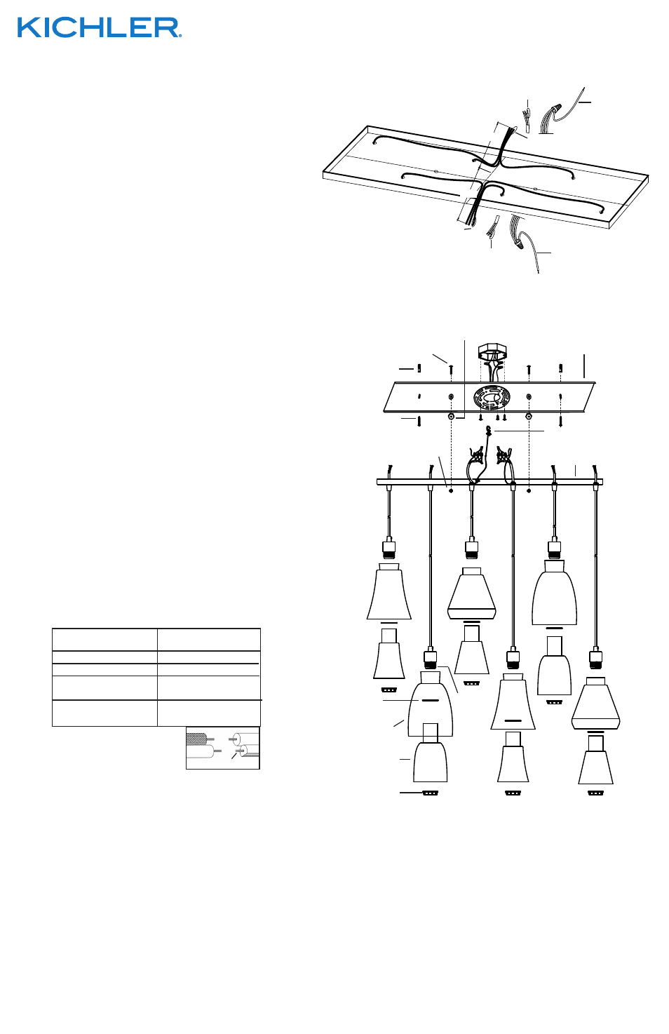
13) From the inside of the canopy, gather the three cords from the fixtures running in a
row along the front of the canopy into one group in the center of the canopy.
REF: Fixture wiring detail.
14) Gather the three cords from the fixtures running in a row along the back of the
canopy into a second group in the center of the canopy. REF: Fixture wiring detail.
15) For each cord, from the point where the cord meets in the center of canopy,
measure 6” of cord passed that point. Trim each cord. REF: Fixture wiring detail.
16) For each cord, with wire strippers, remove 2 inches from end of each wire jacket.
Then strip 1/2 inch from end of each color wire. REF: Stripped Wires Detail and
Fixture Wiring Detail.
17) Connect safety cable assembled to canopy to mounting bracket. (This will allow
for fixture to be supported while wire connections are made.)
18) Connect fixture ground wire to outlet box ground wire with wire connector. (Not
provided.) Never connect ground wire to black or white power supply wire.
19) Connect each black wire together with one black jumper wire with wire connector.
REF: Fixture wiring detail.
20) Connect each green wire together with one green jumper wire with wire connector.
REF: Fixture wiring detail.
21) Connect each white wire together with one white jumper wire with wire connector.
REF: Fixture wiring detail.
22) Make wire connections (connectors not provided.) Reference chart below for
correct connections and wire accordingly.
23) Push fixture to ceiling, carefully passing mounting screws on mounting bracket
through each hole in canopy. CAUTION: Be careful not to pinch wires between
canopy and ceiling.
24) Screw threaded balls onto mounting screws. Tighten mounting screws to secure
fixture to ceiling.
25) Raise outer glass shade up to fixture. Pass hole in outer glass shade over socket.
26) Slip spacer over socket inside outer glass shade.
27) Raise inner glass shade up to fixture. Pass hole in inner glass shade over socket.
28) Thread socket ring onto socket. Tighten socket ring to secure glass in place. (DO
NOT over tighten.)
Connect Black or
Red Supply Wire to:
Connect
White Supply Wire to:
Black
White
*Parallel cord (round & smooth)
*Parallel cord (square & ridged)
Clear, Brown, Gold or Black
without tracer
Clear, Brown, Gold or Black
with tracer
Insulated wire (other than green)
with copper conductor
Insulated wire (other than green)
with silver conductor
*Note: When parallel wires (SPT I & SPT II)
are used. The neutral wire is square shaped
or ridged and the other wire will be round in
shape or smooth (see illus.)
Neutral Wire
Date Issued: 10/24/14
IS-43628-CB
We’re here to help
866-558-5706
Hrs: M-F 9am to 5pm EST
INSTRUCTIONS
For Assembling and Installing Fixtures in Canada
Pour L’assemblage et L’installation Au Canada
SEE OTHER SIDE FOR CANADIAN FRENCH TRANSLATIONS.
VOIR L’AUTRE CÔTÉ POUR LES CANADIENS TRADUCTIONS EN
FRANÇAIS.
FIXTURE WIRING DETAIL
DÉTAILS DU CÂBLAGE DU LUMINAIRE.
6"
6"
FOR EACH COLOR WIRE
POUR CHAQUE FIL DE COULEUR
JUMPER WIRE
CAVALIER
CORD
CORDÓN
MOUNTING BRACKET
SUPPORT DE FIXATION
MOUNTING SCREW
VIS DE MONTAGE
THREADED BALL
BOULE FILETÉ
CANOPY
CACHE
JUMPER WIRE
CAVALIER
CORD
CORDÓN
FOR EACH COLOR WIRE
POUR CHAQUE FIL DE
COULEUR
SCREW
VIS
ANCHOR
ANCRAGE
SAFETY CABLE
CÂBLE DE SÉCURITÉ
HEXNUT
ECROU HEXAGONAL
CORD
CORDON
STRAIN RELIEF
RÉDUCTEUR DE
TENSION
SOCKET RING
ANNEAU DE LA
DOUILLE
OUTER GLASS SHADE
ABAT-JOUR DE VERRE
EXTÉRIEURE
SPACER
ENTRETOISE
INNER GLASS SHADE
ABAT-JOUR DE VERRE
INTÉRIEURE
SOCKET
DOUILLE