Kichler 42172 Manuel d'utilisation
Luminaires Kichler
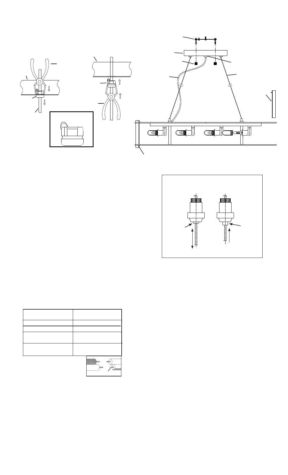
Adjusting position of fixture after installation for leveling purposes of
one inch or less:
NOTE: Center cable will adjust height of fixture. Side cables will adjust level
of fixture.
TO RAISE FIXTURE: Push cable up into fixture body. Release cable and
cable will lock into place.
TO LOWER FIXTURE: Push button in on cable adjuster and pull cable
down. Release button to lock cable in place.
NOTE: With button pushed in cable will raise and lower. Without button
pushed in cable will only raise up and lock in place. (SEE: CABLE ADJUST-
MENT DETAIL)
IMPORTANT SAFETY INSTRUCTIONS
LIGHTED BULB IS HOT!
WARNING: To reduce the risk of FIRE or INJURY TO PERSON:
• Turn off and allow to cool before replacing bulb.
• Bulb gets HOT QUICKLY! Contact switch only when turning off.
• DO NOT remain in light if skin feels warm. (Light is intense, may cause
“sunburn”)
• DO NOT look directly at lighted bulb.
• Keep materials away from bulb that may burn.
• Use ONLY with wattage specified or lower.
• DO NOT touch bulb at any time, use a soft cloth. Oil from skin may damage
bulb.
• DO NOT operate fixture with missing or damaged glass.
1) TURN OFF POWER.
IMPORTANT: Before you start, NEVER attempt any work without
shutting off the electricity until the work is done.
a) Go to the main fuse, or circuit breaker, box in your home. Place
the main power switch in the “OFF” position.
b) Unscrew the fuse(s), or switch “OFF” the circuit breaker switch(s),
that control the power to the fixture or room that you are working on.
c) Place the wall switch in the “OFF” position. If the fixture to be
replaced has a switch or pull chain, place those in the “OFF”
position.
2) Assemble mounting screws into threaded holes in mounting strap.
3) Attach mounting strap to outlet box. (Screws not provided)
4) Make wire connections (connectors not provided.) Reference chart
below for correct connections and wire accordingly.
IMPORTANT: For fixtures 42172, 42173 and 42174, the wires on these
fixtures will be clear or silver. The “Black” fixture wire should be marked with
an “L”. The “White” fixture wire should be marked with an “N”. The “White”
supply wire does have a thin white wire that runs through the clear/silver wire.
5) Push fixture to ceiling, carefully passing mounting screws through holes.
6) Secure fixture to ceiling with threaded balls.
8) Insert recommended bulb. CAUTION: DO NOT touch bulb with bare
hands. If this happens, clean bulb with denatured alcohol and a lint free
cloth.
9) Thread glass sleeve onto socket. (DO NOT over tighten.)
10) Lower each crystal rod down through top and bottom triangular opening
on fixture. Peg on crystal will keep crystal in place on fixture.
Connect Black or
Red Supply Wire to:
Connect
White Supply Wire to:
Black
White
*Parallel cord (round & smooth)
*Parallel cord (square & ridged)
Clear, Brown, Gold or Black
without tracer
Clear, Brown, Gold or Black
with tracer
Insulated wire (other than green)
with copper conductor
Insulated wire (other than green)
with silver conductor
*Note: When parallel wires (SPT I & SPT II)
are used. The neutral wire is square shaped
or ridged and the other wire will be round in
shape or smooth (see illus.)
Neutral Wire
MOUNTING STRAP
COLLLIER DE FIXATION
Date Issued: 6/8/12
IS-42172-CB
INSTRUCTIONS
For Assembling and Installing Fixtures in Canada
Pour L’assemblage et L’installation Au Canada
PRESSED
CABLE ADJUSMENT DETAIL
DÉTAILS D’AJUSTEMENT DU CÂBLE
NOT
PRESSED
UP & DOWN
UP ONLY
FIXTURE
LUMINAIRE
THREADED BALL
BOULE FILETÉ
SIDE CABLE
CABLE LATERAL
CRYSTAL ROD
TIGE EN CRISTAL
TRIANGULAR OPENING
OUVERTURE TRIANGULAIRE
SEE OTHER SIDE FOR CANADIAN FRENCH TRANS-
LATIONS.
VOIR L’AUTRE CÔTÉ POUR LES CANADIENS TRA-
DUCTIONS EN FRANÇAIS.
STRAIN RELIEF
SERRE-CÂBLE
WIRE
FILS
1) If strain relief is not assembled to wires, pull wires up through strain
relief and close strain relief.
2) Holding strain relief with pliers, pinch sides of strain relief and push
strain relief up through hole in canopy. (REF: FIG. 2)
3) If strain relief is assembled to canopy, to remove strain relief to
release strain on wires, from inside canopy pinch sides of strain relief
with pliers. Push strain relief down through hole in canopy. (REF: FIG. 1)
4) Open strain relief and pull wires down. Close strain relief and replace
strain relief to canopy (see step #2).
CAUTION: Take care not to nick, cut or damage wire.
CANOPY
CACHE
PLIERS
PINCES
STRAIN RELIEF
SERRE-CÂBLE
STRAIN RELIEF
SERRE-CÂBLE
PLIERS
PINCES
CANOPY
CACHE
WIRE
FILS
FIG. 1
FIG. 2
STRAIN RELIEF
SERRE-CÂBLE