Kichler 15474 Manuel d'utilisation
Luminaires Kichler
FOR USE WITH LANDSCAPE LIGHTING SYSTEMS ONLY.
1) The device is accepted as a component of a landscape lighting system
where the suitability of the CSA or UL labeled combination shall be deter
mined by CSA, UL respectively or the local inspection authorities having
jurisdiction.
2) Fixture shall be connected to an extra low voltage transformer approved for
use with landscape lighting systems.
3) This fixture is to be connected to a secondary wiring of the following type:
12 GA 60°C minimum type;
SPT-3 suitable for outdoor use; or
approved landscape lighting cable.
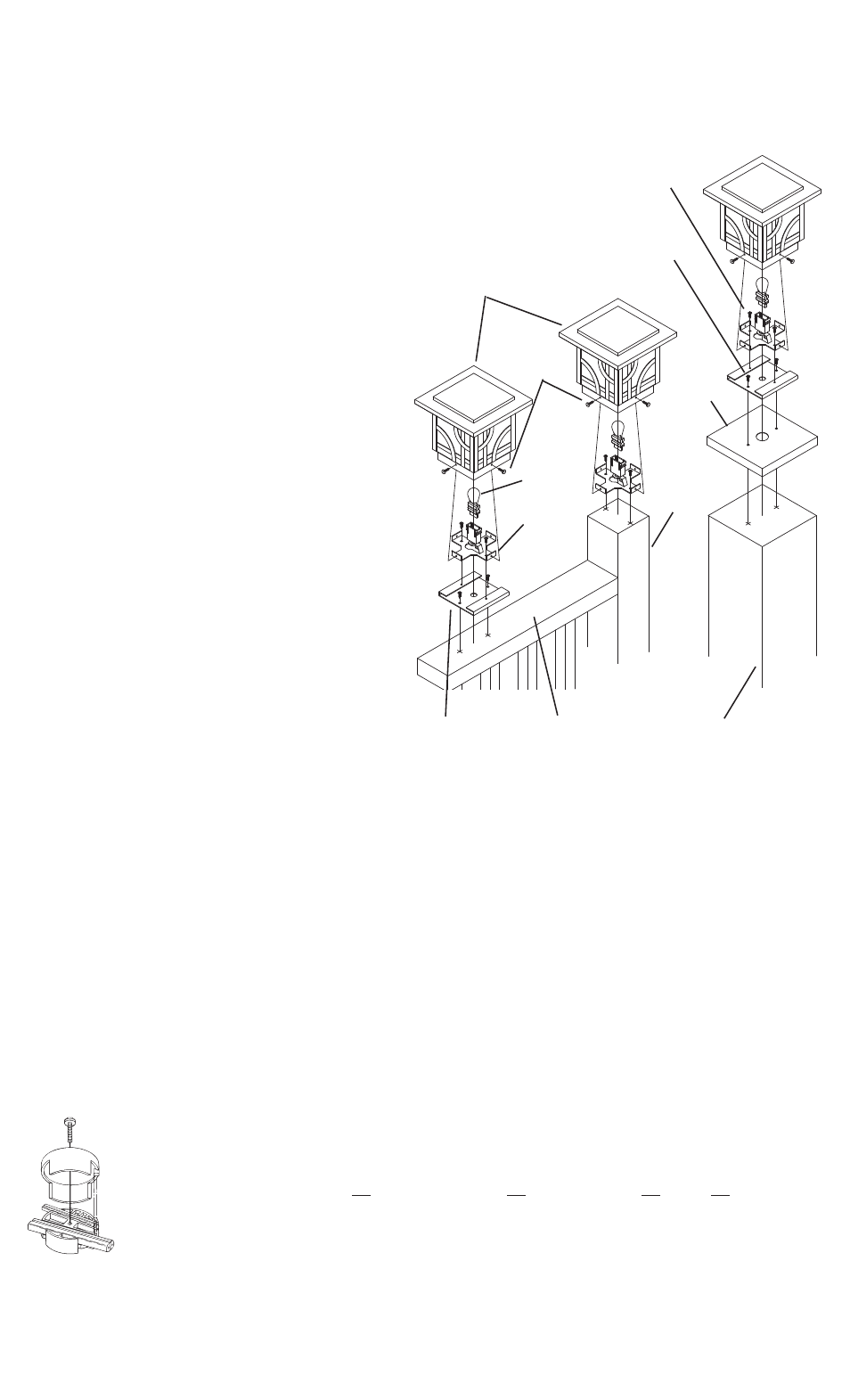
4” X 4” POST APPLICATION ASSEMBLY INSTRUCTIONS - SEE FIG. 2
1) Remove thumbscrews from bottom of fixture head and remove post
adapter from inside fixture head.
2) Place post adapter on top of post allowing equal distances on all sides.
3) Mark position of mounting holes on top of post and remove post adapter.
4) Drill pilot holes in top of post in locations marked in step 3.
5) Drill hole for wire way.
6) Using provided wood screws assemble post adapter to top of post.
7) Install provided bulb to socket inside fixture body
8) Re-assemble fixture head to post adapter..
9) TURN OFF POWER.
10) Make wire connections using supplied Quic Disc
™
following instructions
below, or using other approved wiring connection method (not supplied.)
RAIL APPLICATION ASSEMBLY INSTRUCTIONS - SEE FIG. 1
1) Place rail adapter on to top of railing with mounting holes on center of railing.
2) Mark position of mounting holes and wire way hole on top of railing and
remove rail adapter.
3) Drill pilot holes in top of railing in locations marked in step 2.
4) Drill hole suitable for wire to pass through in position marked in step 2.
5) Using provided wood screws assemble rail adapter to top of railing.
6) Remove thumbscrews from bottom of fixture head and remove post
adapter from inside fixture head.
7) Pass wire through hole and place post adapter on top of rail adapter and
secure in place using provided sheet metal screws.
8) Install provided bulb to socket.
9) Re-assemble fixture head to post adapter.
10) TURN OFF POWER.
11) Make wire connections using supplied Quic Disc
™
following instructions
below, or using other approved wiring connection method (not supplied.)
6” X 6” POST APPLICATION ASSEMBLY INSTRUCTIONS - SEE. FIG. 3
1) Place post cap on top of post.
2) Mark position of mounting holes on top of post and remove post cap.
3) Drill pilot holes in top of post in locations marked in step 2.
4) Drill hole for wireway.
5) Replace post cap on top of post.
6) Place rail adapter on top of post cap aligning mounting holes of cap and
adapter.
7) Using provided wood screws assemble rail adapter and post cap to top of
post.
8) Remove thumbscrews from bottom of fixture head and remove post
adapter from inside fixture head.
9) Pass wire through hole and place post adapter on top of rail adapter and
secure in place using provided sheet metal screws.
10) Install provided bulb to socket.
11) Re-assemble fixture head to post adapter.
Date Issued: 5/7/10
IS-15474-CB
OUTDOOR USE ONLY
DOM ETRE INSTALLE A L’EXTERIEUR
INSTRUCTIONS
For Assembling and Installing Fixtures in Canada
Pour L’assemblage et L’installation Au Canada
WARRANTY
WE WARRANT THE LANDSCAPE PRODUCTS FEATURED IN OUR LANDSCAPE LIGHTING CATALOG (WITH THE EXCEPTION OF LIGHT BULBS) FOR FIVE YEARS AGAINST DEFECTS IN
MATERIALS AND WORKMANSHIP IF IT WAS PROPERLY INSTALLED AND FAILED UNDER NORMAL OPERATING CONDITIONS, PROVIDED IT IS RETURNED TO THE POINT OF PURCHASE,
WHERE IT WILL BE REPAIRED OR, AS IT MAY BE DETERMINED, TO REPLACE THE LANDSCAPE PRODUCT OR PARTS USED ON THAT PRODUCT.
Quic Disc
™
WIRING INSTRUCTIONS
Turn off power.
The full length of the 18 GA fixture wire may be used to connect with the 10 GA or 12 GA cable provided the following conditions are met:
• Wiring is to be protected by routing close to the fixture or accessory or secured to a building structure such as house or deck.
• 18 GA fixture wiring is to be cut off so that it is attached to the connector within 6 inches of the fixture or building structure.
• If it is necessary to make the connections underground, then no more than 6 inches of the 18 GA fixture wire is to be buried.
The Quic Disc
™
connector is designed to install one fixture and accommodates one 18 GA fixture wire and one 10 GA or one 12 GA supply wire.
Place the 10 gauge supply wire across the area marked 10 GA on Quic Disc
™
or place the 12 gauge supply wire across the area marked 12 GA
on Quic Disc
™
.
Place the 18 gauge fixture wire across the area marked 18 GA on the Quic Disc
™
. After the wires are in place, connecta the top of the Quic
Disc
™
to the base with supplied screw, making sure that the wires remain flat in the bottom portion of the Quic Disc
™
, and the screw is tightened
all the way down.
The copper contacts will automatically pierce the wires’ insulation. Excess 18 GA fixture wire that sticks out the end of the Quic Disc
™
is to be cut off.
Make no other wiring connections to the 18 GA fixture wire.
FIG. 1
FIG. 2
FIG. 3
RAILING
CARRIL
BULB
BOMBILLA
RAIL ADAPTER
ADAPTADOR
DEL RIEL
POST ADAPTER
ADAPTADOR DEL
POSTE
THUMBSCREW
TORNILLO DE
APRIETE
FIXTURE HEAD
CABEZA DEL ARTEFACTO
4” SQ. POST
MONTANT
4 PO M2
6” SQ. POST
MONTANT
6 PO M2
SHEET METAL SCREW
VIS DE TOLE
WOOD SCREW
VIS POUR LE BOIS
POST CAP
BOUCHON
MONTANT