General description, External connection, Antenna connection – Curtis PLCD5092A-D Manuel d'utilisation
Page 7: Connecting vcr, Installing batteries in the remote control
COAXIAL
OUT
RF
IN
VGA
IN
PC AUDIO
IN
HDMI 1
HDMI 2
HDMI 3
Pr
VIDEO R
L
VIDEO R
Pb
Y
L
OUT
7
8
Installing Batteries in the Remote Control
Installing Batteries
1
Open the battery compartment
cover on the back side.
2
Insert two 1.5V AAA size batteries in
correct polarity. Don´t mix old or used
batteries with new ones.
3
Closed the cover.
Point the remote towards the remote
control sensor of the wireless TV and
use it within 7 meters.
Put the used batteries into the recyc-
ling bin since it can negatively affect
the environment.
General Description
Battery
Cover
2xsize AAA 1.5V
Battery
Cover
Antenna connection
Antenna input impedance of this unit is 75ohm. VHF/UHF 75ohm coaxial cable can be
connected to the antenna jack directly, if the antenna cable is 300ohm parallel flat feeder
cable, you need to use the 300ohm/75ohm converter to connect the antenna cable to the
antenna jack. For details Please refer to the following drawing.
Use a 75ohm - 300ohm converter
300ohm coaxial cable
Antenna feeder
ANT IN
75ohm coaxial cable
Antenna cable
Antennas with 300
flat twins Leads
ohm
Antennas with 75
Round Leads
ohm
External Connection
The batteries shall not be eposed to ecessive heat such as sunshine
fire of the like.
External Connection
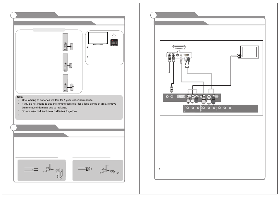
Connecting VCR
These instructions assume that you have already connected your TV to an antenna or a
cable TV system. Skip step 1 if you have not yet connected to an antenna or a cable
system.
Follow the instructions in Viewing a VCR or Camcorder Tape to view your VCR tape.
Each VCR has a different back panel configuration.
When connecting a VCR, match the color of the connection terminal to the cable.
We recommend the use of cables with a Ferrite Core.
1. Unplug the cable or antenna from the back of the TV.
2. Connect the cable or antenna to the ANT IN terminal on the back of the VCR.
3. Connect an RF Cable between the ANT OUT terminal on the VCR and the ANT IN
terminal on the TV.
4. Connect a Video Cable between the VIDEO OUT jack on the VCR and the VIDEO IN
jack on the TV.
5. Connect Audio Cables between the AUDIO OUT jacks on the VCR and the AUDIO L and
AUDIO R jacks on the TV.
If you have a mono (non-stereo) VCR, use a Y-connector (not supplied) to hook up to
the right and left audio input jacks of the TV. If your VCR is stereo, you must connect
two cables.
VCR Rear Panel
RF Cable
(Not supplied)
Video Cable
(Not supplied)
Audio Cable
(Not supplied)
Note: The AV output can be used only when the input signal is AV or TV.
TV
TV AV INPUT
SERVICE
PORT