Sloan WES 2000 Installation Manuel d'utilisation
Wes-2000, Waterfree urinal installation instructions
2” side cutter blade
1
2
3
4
5
6
7
10
11
12
13
14
15
8
9
16
17
18
19
Put
additional
screws here
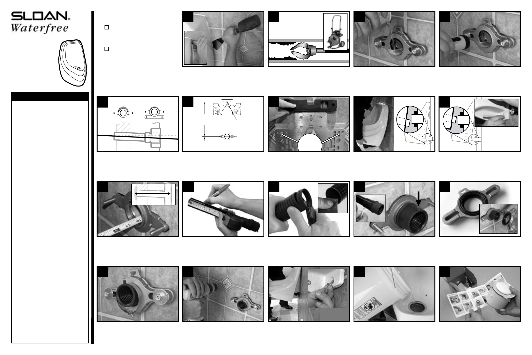
Use utility knife to cut caulk, then use
a putty knife and mallet to remove the
bowl. Remove hanger brackets, scrape
off caulk, and clean the wall.
Important: Use a drain machine to
remove build-up inside pipes. Clean
25-35 feet deep then flush with water
to remove cutting debris.
Clean face of existing wall flange then
install the brass flange with the clear
inspection disc. Slowly pour water into
the drain.
Use a flashlight to check pitch/slope.
There should be no water present in
the inspection disc or nipple. Remove
flange after inspection.
If standing water is present, adjust drain
to achieve pitch (code requires 1/4”
drop per foot of drain line for proper
pitch). Seal wall according to code.
Measure and mark the rough-in. Use
a 5/16” masonry bit to drill hole, then
install the hanger bracket with one
plastic anchor and screw.
Level the bracket then mark, drill and
install two additional plastic anchors
and screws. If pre-existing bearing rods
can be used, screws are not necessary.
Determine the drain nipple depth by
measuring the distance between the
back of the sanitary tee (or elbow) to
the front edge of the brass flange.
Find the drain nipple depth on the
cutting chart (left) and mark the
specified trim length on the insert tube
at the nearest 1/4” groove.
Cut the tube at the groove using a
sharp utility knife to ensure a square,
flat cut. Clean burrs from the cut end
with emery paper.
Apply lubricant to the outside of the rub-
ber bushing and ribbed inside area. Insert
the tube and bushing with the arrow tab
at the top. Lube tailpipe of housing.
Place the seal into the flange with
the ribs facing out. Install the flange
with washers and hex nuts, but do not
tighten completely.
Install the gear clamp with the screw
head at the bottom, but do not tighten.
Hang the bowl on the bracket and
check tail pipe alignment, then remove
the bowl and adjust the bracket as
needed.
Re-hang and re-check bowl alignment
with the drain line. Mark anchor holes
then remove the bowl without moving
the hanger bracket.
Drill holes for the lower anchor screws
and insert plastic anchors.
Hang the bowl, inserting tailpipe into
bushing, then install anchor screws
with washers. Tighten flange bolts and
gear clamp.
Pour 5 gallons of water as rapidly as
possible into housing to ensure good
flow and no leaks or standing water.
Caulk bowl to the wall. Install the
cartridge per the cartridge instruction
sheet.
Incorrect
Correct
Arrow Tab UP
Insert Tube Cutting Chart
Drain Nipple Depth Trim
13 7/8” or greater. . . . Do not cut
13 3/4” or less . . . . . . 1/4”
13 1/2” or less . . . . . . 1/2”
13 1/4” or less . . . . . . 3/4”
13”
or less . . . . . . 1”
12 3/4” or less . . . . . . 1 1/4”
12 1/2” or less . . . . . . 1 1/2”
12 1/4” or less . . . . . . 1 3/4”
12”
or less . . . . . . 2”
11 3/4” or less . . . . . . 2 1/4”
11 1/2” or less . . . . . . 2 1/2”
11 1/4” or less . . . . . . 2 3/4”
11”
or less . . . . . . 3”
10 3/4” or less . . . . . . 3 1/4”
10 1/2” or less . . . . . . 3 1/2”
10 1/4” or less . . . . . . 3 3/4”
10”
or less . . . . . . 4”
9 3/4” or less . . . . . . 4 1/4”
9 1/2” or less . . . . . . 4 1/2”
9 1/4” or less . . . . . . 4 3/4”
9”
or less . . . . . . 5”
8 3/4” or less . . . . . . 5 1/4”
8 1/2” or less . . . . . . 5 1/2”
8 1/4” or less . . . . . . 5 3/4”
8”
or less . . . . . . 6”
7 3/4” or less . . . . . . 6 1/4”
7 1/2” or less . . . . . . 6 1/2”
7 1/4” or less . . . . . . 6 3/4”
7”
or less . . . . . . 7”
6 3/4” or less . . . . . . 7 1/4”
6 1/2” or less . . . . . . 7 1/2”
6 1/4” or less . . . . . . 7 3/4”
6”
or less . . . . . . 8”
5 3/4” or less . . . . . . 8 1/4”
5 1/2” or less . . . . . . 8 1/2”
5 1/4” or less . . . . . . 8 3/4”
5”
or less . . . . . . 9”
4 3/4” or less . . . . . . 9 1/4”
4 1/2” or less . . . . . . 9 1 /2”
4 1/4” or less . . . . . . 9 3/4
4”
or less . . . . . . 10”
3 3/4” or less . . . . . . Do not
use tube
Install plastic
anchor and
screw here
Cut away wall
Lift drain line and
brace with a mending plate
Tail pipe should
align with center
of drain line
Before Starting Installation:
Check rough-in height to
achieve 24” rim height
(17” rim height for ADA).
Shut off water supply and
cap the nipple with the
3/4” chrome cap (provided).
18”
(457 mm)
16
5
/
8
” from finished floor for
standard 24” rim height (9
5
/
8
” for ADA)
wes-2000
Waterfree
Urinal
Installation
Instructions
The information in this document is subject to change without notice. © 2006 Sloan Valve Company. All rights reserved. 0816579, Rev 0 (10/06)
Customer Care:
Toll Free 888-SLOAN-14 (888-756-2614)
Fax 800-737-3061 • www.sloanvalve.com