RISCO Group 2-Way Wireless Magnetic / Door Contact RWX73M Manuel d'utilisation
Relais RISCO Group
RTTE Compliance Statement
Hereby, RISCO Group declares that this equipment is in
compliance with the essential requirements and other
relevant provisions of Directive 1999/5/EC. For the CE
Declaration of Conformity please refer to our website:
www.riscogroup.com
MAIN FEATURES
The RWX73M is a 2-way supervised transmitter that
combines the Magnetic/Door Contact (against opening doors
and windows) with an additional universal input or shutter.
The RWX73M operates with RISCO’s 2-way wireless
systems.
NORMALLY CLOSED
INPUT CONFIGURATION
NORMALLY OPEN INPUT
CONFIGURATION
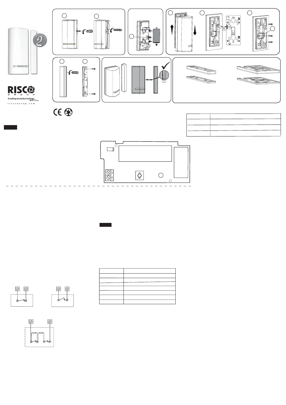
Step 2: Input Wiring
Use the following diagrams for appropriate input
termination wiring. For DEOL termination connect
two 10 K Ohm resistors (supplied) illustrated as follows:
ALARM
DETECTOR
ALARM
DETECTOR
INSTALLATION
Ɣ Communication: Bi-directional
Ɣ Range: up to 300 m (1,000 ft.) range line of sight
Ɣ Supervision: Up to 255 minutes
Ɣ Selective input termination : NO, NC, DEOL, shutter
Ɣ Selective input response: 10 / 500 ms
Ɣ Tamper protection: back + cover
Step 1: Transmitter-to-Receiver Communication Setup
The RWX73M must identify itself to the system's receiver
by writing its coded message into the receiver's address
memory.
This registration is performed either by entering the
RWX73M’s 11-digit serial code number or by performing
the following RF allocation steps:
1. Remove the front cover (Fig 1)
2. Set the main unit to Learn mode.
3. Remove the battery from the insulation material and
reinsert it into the transmitter, paying attention to the
polarity (Fig. 2).
4. Send a write message by pressing the front tamper
switch (without detaching the back bracket) for at least
3 seconds until panel recognition is displayed (Fig. 2).
NOTE: Wait at least 1 minute before closing the front cover.
DOUBLE END OF LINE INPUT CONFIGURATION
10k
ALARM
TAMPER
10k
DETECTOR
Step 3: Selecting the Mounting Location
1. Select a location best suited for communication quality
and near the intended wired detector. It is recommended
to place the unit at the highest possible position.
2. Temporarily attach the unit to this point using two-sided
adhesive tape.
3. Generate an alarm signal (by momentarily opening or
closing the input terminals) and verify that the receiver
has received the signal. If the alarm signal is not
detected, reposition the transmitter and try again.
Step 4: Mounting (Fig. 3 -- Fig. 6)
1. Detach the back of the transmitter from the back bracket
(Fig. 3A). At mounting location note the alignment marks
for both components (Fig. 3B), and then install accordingly
2. Detach magnet casing (Fig. 4A) and install with mounting
Notes:
3. The mark on the magnet's case must be aligned with
the mark on the transmitter's case (Fig. 5).
4. For installations on wood or alloy, the maximum distance
for normal operation is 10 mm (1 cm), while for metal
ferromagnetic materials (such as iron) it is 5 mm (Fig. 5).
TAMPER SW1
LED
BATTERY
ANTENNA
+
-
C RISCO
IN2
T.B
Step 5: De
¿ning Parameters
The following parameters can be de
¿ned for RWX73M:
Parameter Option
Supervision Yes/No
LED Enable Yes/No
Magnet
Enable/Disable
Alarm Hold On/Off
Termination IN2: NO/NC/DEOL/Shutter
TECHNICAL SPECIFICATIONS
ELECTRICAL
Battery Type:
CR123 3V Lithium Battery
Current Consumption: 11
A standby
Frequency: RWX73M86800B 868.65 MHz
RWX73M43300B 433.92 MHz
Dead Time (HOLD ON): 2.5 minutes
Supervision Transmission: 0-255 minutes
Modulation Type:
ASK
Battery Life:
3 years typical
Contact Size: 32 x 35 x 72 mm (1.3 x 1.4 x 2.8 in.)
Magnet Size: 16 x 11 x 72 mm (0.6 x 0.44 x 2.8 in.)
ENVIRONMENTAL
RF immunity:
According to EN 50130-4
Operating temperature: -10° C to 55° C (14° F to 131° F)
Storage temperature: -20° C to 60° C (-4° F to 140° F)
Speci
¿cations are subject to change without prior notice.
Should any questions arise please contact your supplier.
LED INDICATION
Ɣ Upon successful learning: short Àash sequence
Ɣ Normal operation: brief light upon transmission
Ɣ Low battery: short Àash sequence during transmission
EN 50131-2-6 Grade 2 Environmental Class II
2-Way Wireless
Magnetic Door/Window Contact
with Shutter
(Model RWX73M)
© RISCO Group 10/2014
5IN2255 B
Response 10 ms / 500 ms
The RWX73M reports events from IN2 and from the magnetic
the input or magnet are triggered. When restored, it transmits
RISCO Group Limited Warranty
RISCO Group and its subsidiaries and af
¿liates ("Seller") warrants its
products to be free from defects in materials and workmanship under
normal use for 24 months from the date of production. Because Seller
does not install or connect the product and because the product may
be used in conjunction with products not manufactured by the Seller,
Seller cannot guarantee the performance of the security system
which uses this product. Seller's obligation and liability under this
warranty is expressly limited to repairing and replacing, at Seller's
option, within a reasonable time after the date of delivery, any product
not meeting the speci
¿cations. Seller makes no other warranty,
expressed or implied, and makes no warranty of merchantability or of
¿tness for any particular purpose. In no case shall seller be liable for
any consequential or incidental damages for breach of this or any
other warranty, expressed or implied, or upon any other basis of
liability whatsoever.
Seller's obligation under this warranty shall not include any transporta-
tion charges or costs of installation or any liability for direct, indirect,
or consequential damages or delay. Seller does not represent that its
product may not be compromised or circumvented; that the product
will prevent any personal injury or property loss by burglary, robbery,
¿re or otherwise; or that the product will in all cases provide adequate
warning or protection.
Seller, in no event shall be liable for any direct or indirect damages or
any other losses occurred due to any type of tampering, whether
intentional or unintentional such as masking, painting or spraying on
the lenses, mirrors or any other part of the detector.
Buyer understands that a properly installed and maintained alarm
may only reduce the risk of burglary, robbery or
¿re without warning,
but is not insurance or a guaranty that such event will not occur or that
there will be no personal injury or property loss as a result thereof.
Consequently seller shall have no liability for any personal injury,
property damage or loss based on a claim that the product fails to
give warning. However, if seller is held liable, whether directly or
indirectly, for any loss or damage arising under this limited warranty
or otherwise, regardless of cause or origin, seller's maximum liability
shall not exceed the purchase price of the product, which shall be
complete and exclusive remedy against seller.
No employee or representative of Seller is authorized to change this
warranty in any way or grant any other warranty.
WARNING: This product should be tested at least once a week.
CAUTION: risk of explosion if battery is replaced by an incorrect type.
Dispose of used batteriess according to local regulations.
Hahoma 14, Rishon Lezion, ISRAEL
Contacting RISCO Group
UK
Tel: +44-(0)-161-655-5500
E-mail: [email protected]
ITALY
Tel: +39-02-66590054
E-mail: [email protected]
SPAIN
Tel: +34-91-490-2133
E-mail: [email protected]
FRANCE
Tel: +33-164-73-28-50
E-mail: [email protected]
BELGIUM
Tel: +32-2522-7622
E-mail: [email protected]
U.S.A
Tel: +1-631-719-4400
E-mail: [email protected]
BRAZIL
Tel: +55-11-3661-8767
E-mail: [email protected]
CHINA
(Hu) Tel: +86-21-52390066
E-mail: [email protected]
CHINA
(SZ) Tel: +86-755-82789285
E-mail: [email protected]
POLAND
Tel: +48-22-500-28-40
E-mail: [email protected]
ISRAEL
Tel: +972-3-963-7777
E-mail: [email protected]
GENERAL DESCRIPTION
English
Max.
1cm
Figure 1
AUSTRALIA
Tel: +1800-991-542
E-mail: [email protected]
T
Shutter pulse 01 - 16
*
B
A
Figure 3
A
Back bracket
Back side of
transmitter
B
Figure 2
T
C
Figure 4
Figure 5
using 2 mounting screws and back tamper screw (Fig 3C).
2. Spacers are purchased separately (see table above).
*
If de
¿ned
OPERATION MODE
A
Spacer Part No. Description
RAX73XS0000A Transmitter spacers x 10, white (5 x 4mm + 5 x 2mm)
RAX73XSB000A Transmitter spacers x 10, brown (5 x 4mm + 5 x 2mm)
RAX73MS0000A Magnet spacers x 10, white (5 x 4mm + 5 x 2mm)
RAX73MSB000A Magnet spacers x 10, brown (5 x 4mm + 5 x 2mm)
1. It’s best to mount the transmitter on the non-moving part
(door/window frame), and the magnet on the moving part.
B
reed switch. In normal operation mode, an alarm is sent when
a restoral message.
screws (Fig 4B).
3. Optionally, mount spacer(s) for transmitter and/or magnet
as required (Fig. 6), positioned between the back bracket
and the mounting surface.
Figure 6
Magnet spacers (10-piece sets):
Transmitter spacers (10-piece sets):
p/n: RAX73MS0000A (white)
p/n: RAX73MSB000A (brown)
p/n: RAX73XS0000A (white)
p/n: RAX73XSB000A (brown)
5 X 4mm
5 X 2mm
5 X 4mm
5 X 2mm
[Optional] [Optional]