Kichler 15065 Manuel d'utilisation
Luminaires Kichler
FOR USE WITH LANDSCAPE LIGHTING SYSTEMS ONLY.
1) The device is accepted as a component of a landscape lighting system
where the suitability of the CSA or UL labeled combination shall be deter
mined by CSA, UL respectively or the local inspection authorities having
jurisdiction.
2) Fixture shall be connected to an extra low voltage transformer approved
for use with landscape lighting systems.
3) This fixture is to be connected to a secondary wiring of the following type:
12 GA 60°C minimum type;
SPT-3 suitable for outdoor use; or
approved landscape lighting cable.
ASSEMBLY AND INSTALLATION
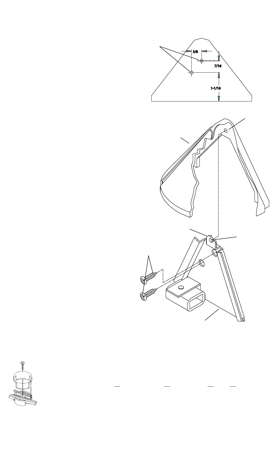
1) Determine desired location for mounting fixture.
2) Using fig. A, mark position for drililng pilot holes and for wireway hole (if
desired).
NOTE: Fig. A is drawn actual size, it can be used as a template or be used
as a template or be referenced for dimensions.
3) Drill 3/32” (2 mm) pilot holes in mounting surface at positions marked. If
using a wireway hole also drill that at this time. Suggested size 1/4” (6 mm).
4) Assemble mounting bracket to mounting surface using provided screws.
5) Carefully slip porcelain shade over mounting bracket. Hole in back of
shade should fit snug between mounting surface and dimple on backside
of tab.
NOTE:: If shade does not seem snug enough or seems too snug, adjust
by slightly bending tab in or out.
6) TURN OFF POWER. Disconnect or unplug transformer.
7) Make wire connections using supplied Quic Disc
™
following instructions
below, or using other approved wiring connection method (not supplied.)
Date Issued: 11/25/11
IS-15065-CB
OUTDOOR USE ONLY
DOM ETRE INSTALLE A L’EXTERIEUR
INSTRUCTIONS
For Assembling and Installing Fixtures in Canada
Pour L’assemblage et L’installation Au Canada
For warranty information please visit: http://www.landscapelighting.com/portal/warranty_page
Pour de plus amples informations sur la garantie, cliquez sur le lien ci-dessous : http://www.landscapelighting.com/portal/warranty_page
QUIC DISC
™
WIRING INSTRUCTIONS
Turn off power.
The full length of the 18 GA fixture wire may be used to connect with the 10 GA or 12 GA cable provided the following conditions are met:
• Wiring is to be protected by routing close to the fixture or accessory or secured to a building structure such as house or deck.
• 18 GA fixture wiring is to be cut off so that it is attached to the connector within 6 inches of the fixture or building structure.
• If it is necessary to make the connections underground, then no more than 6 inches of the 18 GA fixture wire is to be buried.
The Quic Disc
™
connector is designed to install one fixture and accommodates one 18 GA fixture wire and one 10 GA or one 12 GA supply wire.
Place the 10 gauge supply wire across the area marked 10 GA on Quic Disc
™
or place the 12 gauge supply wire across the area marked 12 GA
on Quic Disc
™
.
Place the 18 gauge fixture wire across the area marked 18 GA on the Quic Disc
™
. After the wires are in place, connecta the top of the Quic
Disc
™
to the base with supplied screw, making sure that the wires remain flat in the bottom portion of the Quic Disc
™
, and the screw is tightened
all the way down.
The copper contacts will automatically pierce the wires’ insulation. Excess 18 GA fixture wire that sticks out the end of the Quic Disc
™
is to be cut off.
Make no other wiring connections to the 18 GA fixture wire.
3/8
7/16
1-1/16
WIREWAY HOLE
GUIDE-FIL
PILOT HOLES
AVANT-TROUS
SCREWS
VIS
DIMPLE
CRAN
TAB
PATTE
MOUNTING BRACKET
SUPPORT DE FIXATION
FIG. A
SHADE
ABAT-JOUR